I picked up a Chinese K40 laser cutter a few years back. I played with it and decided the software was abysmal, the controller was horrible, and it was grossly unsafe. I stashed it on the ‘forgotten projects’ shelf and left it there.
Now, since our hackspace is still closed due to COVID-19, I’m really missing our nice Epilog laser cutter. I have all kinds of projects on the go that really need a few small pieces made. I could outsource them, but where’s the fun in that?
So, it really is time to break out the K40 ‘blue box’ and get it up to scratch.
A look Outside
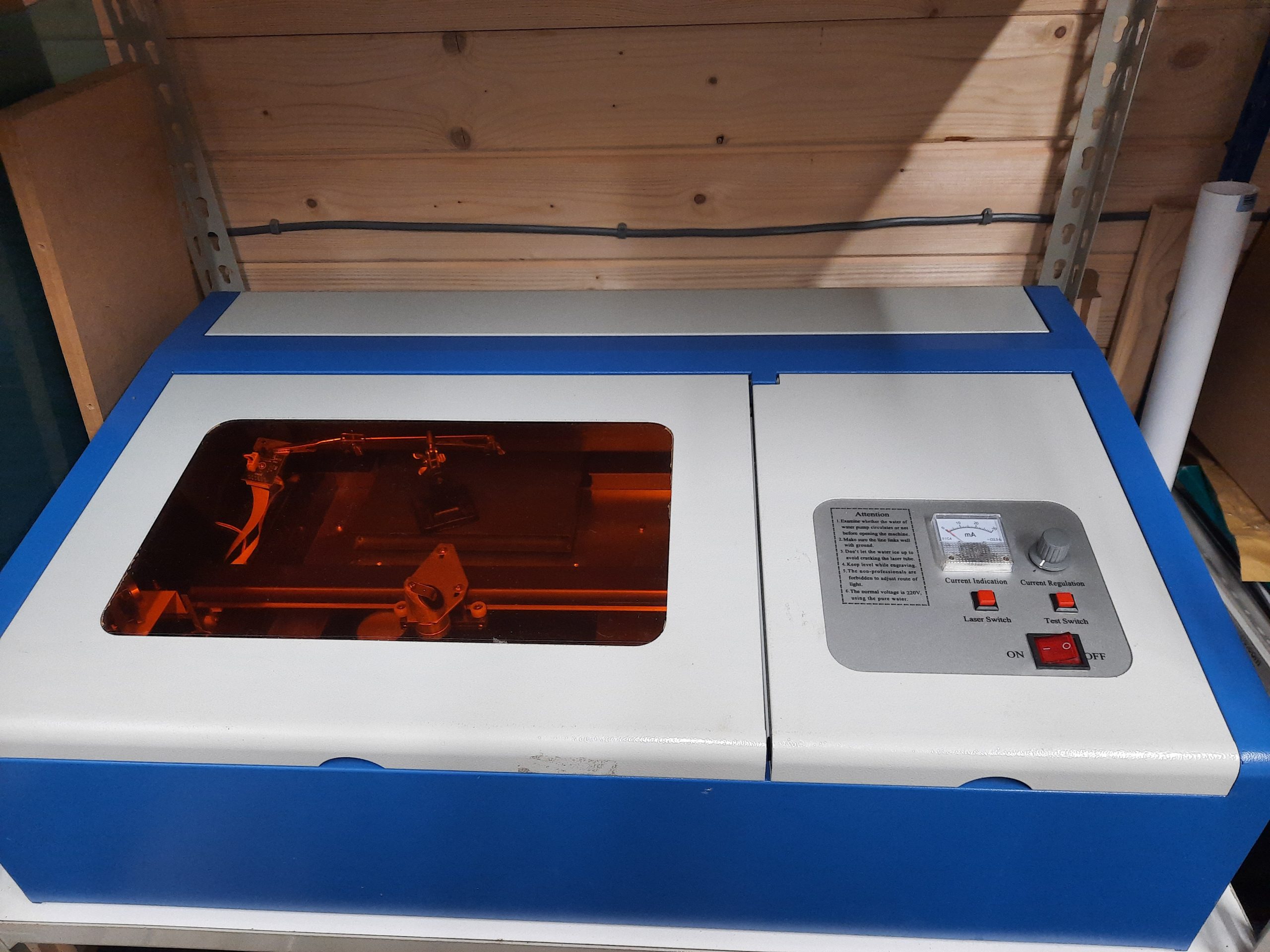
That orange window is just coloured plastic. I have no idea if it specifically absorbs CO2 laser wavelengths, but I’m going to replace it with window glass with a partially reflective film coating. I know for sure that this will block any glancing laser reflections. CO2 lasers cannot penetrate glass; they can only mark it.
Laser Bed
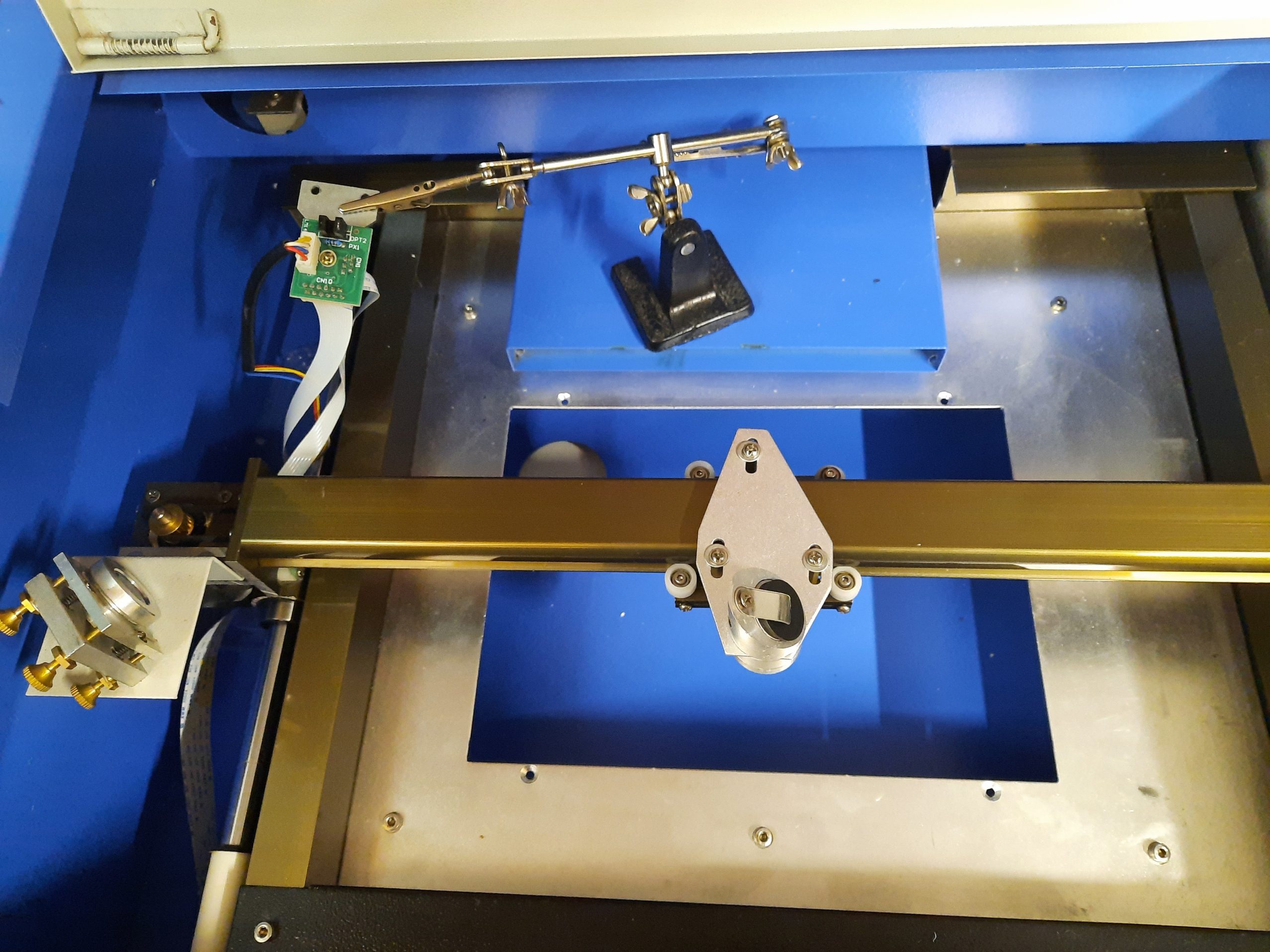
The ‘bed’ was removed to allow measuring the maximum axis travel. There is no Z-height adjustment, so focusing the laser is not possible. I will need to construct my own bed from either expanded metal mesh or honeycomb material. I will be able to make the bed move vertically and in a level manner. It is important that the bed is level with the axes to ensure the laser operating distance is consistent as the axes move.
Quite a bit of mechanical work to do there, and not much space to do it in.
Control Electronics & PSU
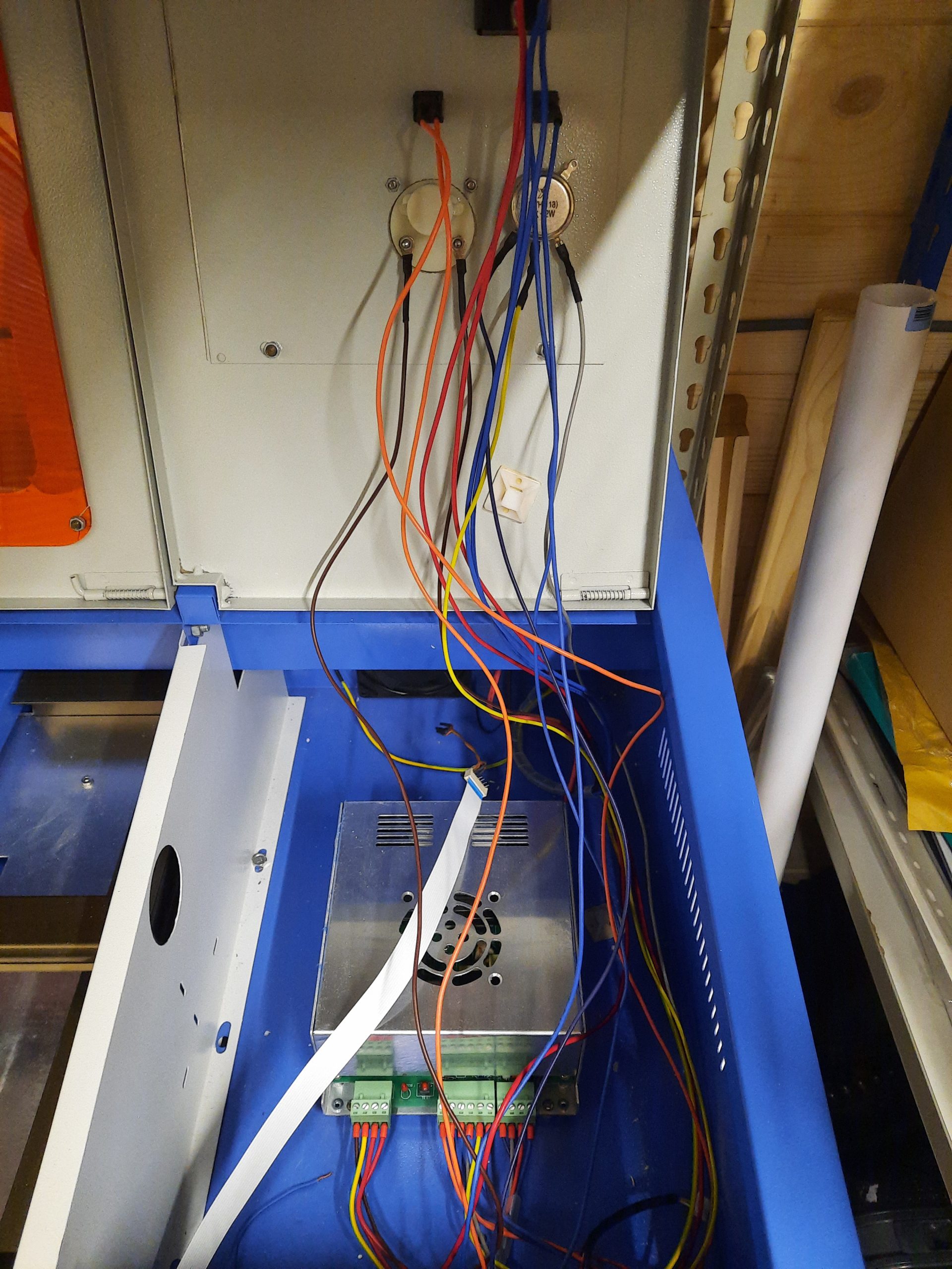
Ugh, where to begin? Too much mixing of line AC and low voltage going on. The earth connection from the laser power supply is screwed to the painted enclosure panel. So not actually connected to it. There is no earth bond to other enclosure sections, or the metal lids.
No interlocks on the access doors, so you can merrily poke your fingers in there whilst it’s running. No shielding over the line input to the 20kV power supply. No strain relief, no grommets where high voltage lines go out through a hole in the metal, etc. This is only a brief summary, it is worse than this, the more you look, the worse it gets.
After stripping off the FPC connectors for the optical end-stops, I threw the original controller PCB in the bin. Somehow in this mess, I need a new front panel, a controller for the motors and laser modulation as well as lots of microswitches on the doors. Perhaps I’ll use hall-effect switches and magnets since I suspect the flimsy steel doors won’t have enough weight to them to reliably close against a micro switch.
Laser Tube Bay
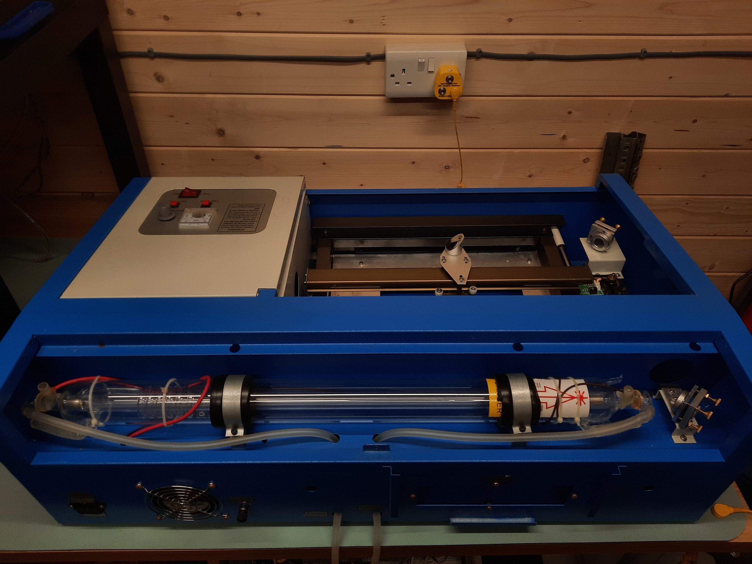
So, is the 20 kv supply connection wrapped around the tube and hot-glued onto the power connection? Awesome.
The water cooling loop consists of a couple of flimsy silicone tubes pushed through some holes in the case. There is no clamping, strain relief, check valves, or flow indicators.
There is no tube temperature sensing, nothing to stop you from putting your face in the beam path, and no interlock on the door.
The water cooling system is simply a pond pump in a bucket of water. There is no filtering, water chiller, temperature sensing, or safety cut-out should the tube overheat and crack, shorting 20 kv into the cooling water. This is scary.
The Plan
- Add an open-source controller, likely just an Arduino Mega running GRBL controlled with LaserWeb on the host side
- Enclose the laser supply connectors
- Redesign the front panel
- Add interlocks on all doors
- Add decent earth bonding everywhere
- Do a better job of the water connection to the tube
- Build a return-flow water chiller with closed-loop temperature control
- Add tube thermal sensing
- Create a level, adjustable-height bed
- Add an air-assist jet to the focusing lens assembly
- Ditch the extraction duct and fit a more powerful fume extraction
Not much then 🙂
From the parts bins
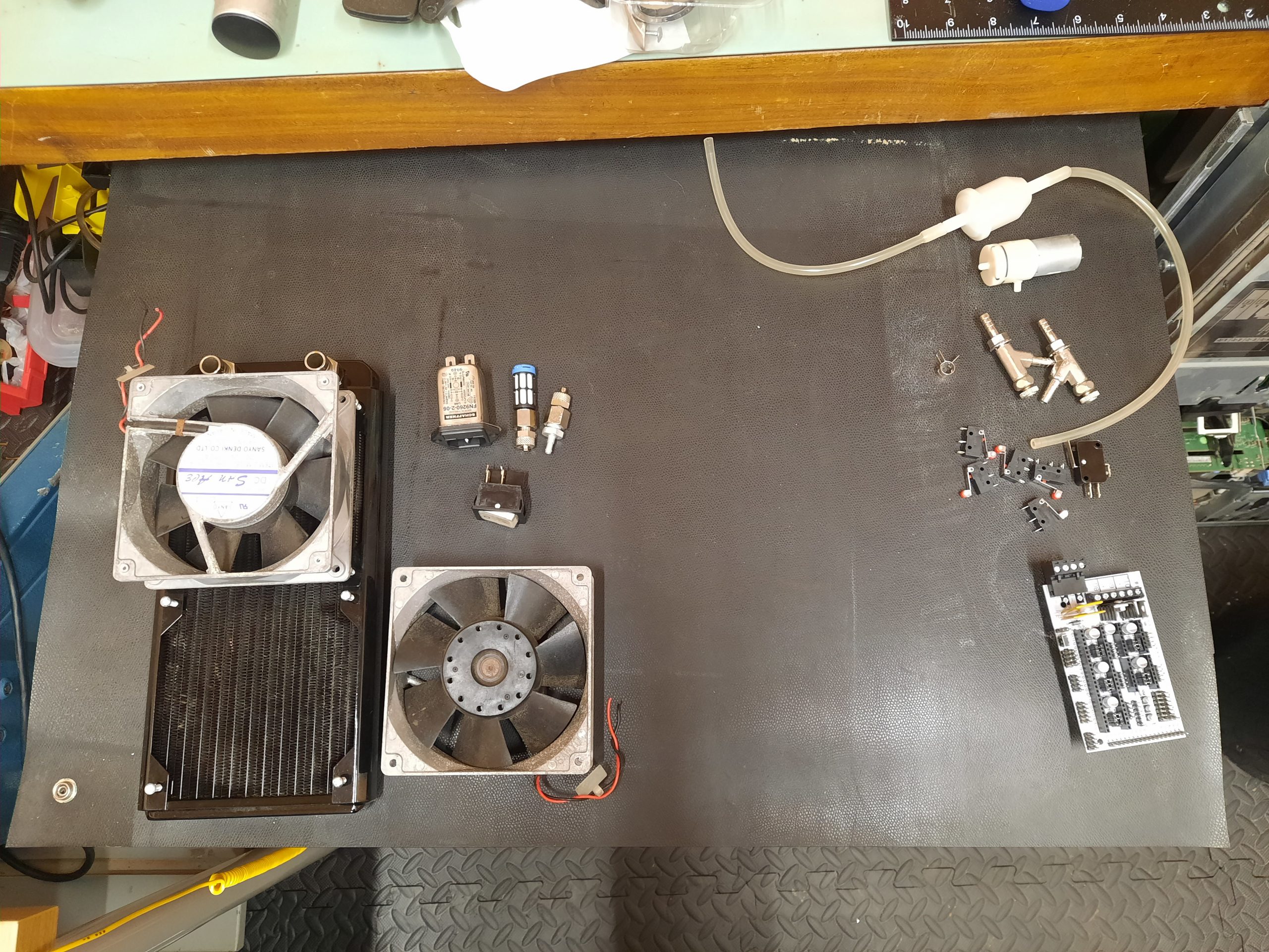
I had a good rummage in my parts bins and found a few bits I could use to help keep the cost down.
On the left are a 120x240mm radiator and old 120mm fans. The latter are powerful and noisy, so I will need speed control there. I also found a fused IEC inlet, an illuminated switch, and a few couplers.
On the right, I found an Arduino-compatible RAMPs-type shield that can host some stepper motor drivers. This will be enough to control the machine. I also found a small air pump (a rotary type) and an air filter, which may or may not be good enough. I even found a couple of air/water valves and some micro switches.
The next job is to hit eBay and find the rest of the parts I need.