Introduction
Early in my electronics prototyping career, I decided that creating a reconfigurable hardware prototyping system would be useful and fun. There are lots of these things around, but none quite worked the way I wanted them to. The premise is simple: make some plastic mounting sheets with a grid of holes and create electronics modules on a case-by-case basis as a particular need arises. Later, these blocks can be remixed and used as the basis of a prototype or even the implementation of a permanent installation.
The Snappit Concept
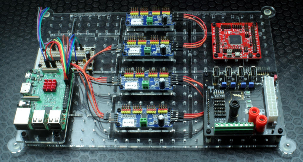
When I create prototypes, I use basic circuits that have been tested and refined over time. I have prototyped projects with different microcontrollers, analog devices, and drivers. This allows me to combine existing designs and quickly create a custom prototype, knowing it will function properly. It’s important to note that these are well-tested circuits. Snappit is an extension of this practice. The existing circuits were integrated into a standalone PCB with connectors and other necessary components. These physical circuits can then be placed onto the Snappit grid and hooked up. Any additional circuits can be built on Veroboard and added to the grid. An adapter plate is used for boards like the Raspberry Pi 3 to ensure they fit on the same grid.
The grid has a pitch of 0.5 inches to accommodate electronic connectors specified with a 0.1-inch resolution. Veroboard has holes with a 0.1-inch pitch. The reason for this non-metric pitch is to create variants of the structure in different sizes for customer prototypes. The ‘large’ plate has slots wide enough to allow wires to pass through comfortably, accommodating Dupont connectors. This design enables stacking multiple plates and flexible cable routing, with options to pass cables out of the bottom.
As I create Snappit boards or work on existing boards, they will be detailed below. For now, only a small number are complete and being used.
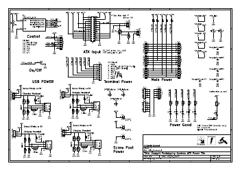
ATX Power
This simple passive power supply adapter provides all the standard ATX supply voltages to various convenient connectors. It’s not meant to be the most cost-effective solution; the main focus is on completeness and ease of use. Each rail is protected with a polyfuse before being connected to the banks of connectors. In this initial version, there are 5v power feeds to the four USB connectors, which work fine for low-power devices, although they are not adequately protected and regulated in this version. Future versions will be upgraded to support USB-C with power delivery (PD). I plan to retain the older USB connectors but safeguard them with current limits and power switches. Usefully, I decided to include a per-port jumper to enable the selection of the 5v or 5v (standby) ATX power rails. This allows some or all USB sockets to stay powered even if the board is shut down and all other rails are unpowered. This is helpful when using the Raspberry Pi (and many other network-connected controllers) since it can simply remain powered and manage the main power supply board by connecting a GPIO channel to a dedicated connector.
The board includes a PIC10F220 microcontroller connected to a push button, which receives a power-good signal from the power supply. This setup enables the board to have a customizable power-up response after recovering from AC power failures and enables custom button behaviours, such as a short push to power up and a long push to power down. Some applications may need to be powered as soon as AC is available, and others may need a connected controller to boot first before it engages the main power supply.
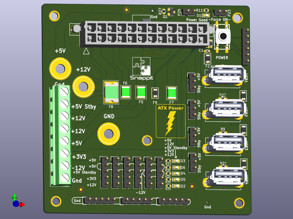
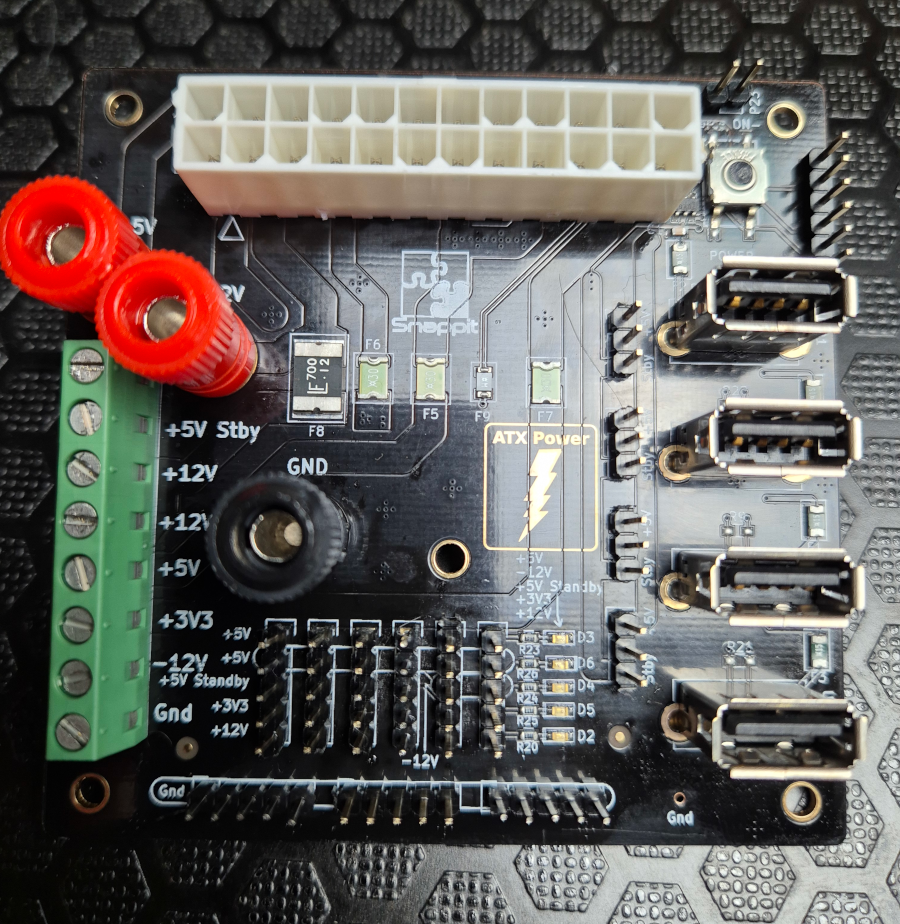
This board has provided power to many installations and prototype builds I’ve worked on over the years. One example is the Vehicle-to-Grid project for Winchester Science Centre. I’ve even built an experimental 3D printer using it, and it handled the power required by the hot end, bed heater, and enclosure heater with no problems. The wide power traces, decent-quality parts, and the extra-thick copper plating I specified for the PCB fab likely helped considerably.
Atmel AVR ATMEGA328
The ATMega328 is the chip that powers the original Arduino UNO. It is still a go-to board for ease of use and learning. Due to its low price and extensive software support, the board is ideal for low-complexity projects. I’ve used so many over the years that I’ve lost count. I decided to take the guts of the Arduino UNO design and make it smaller by removing all the extraneous features.
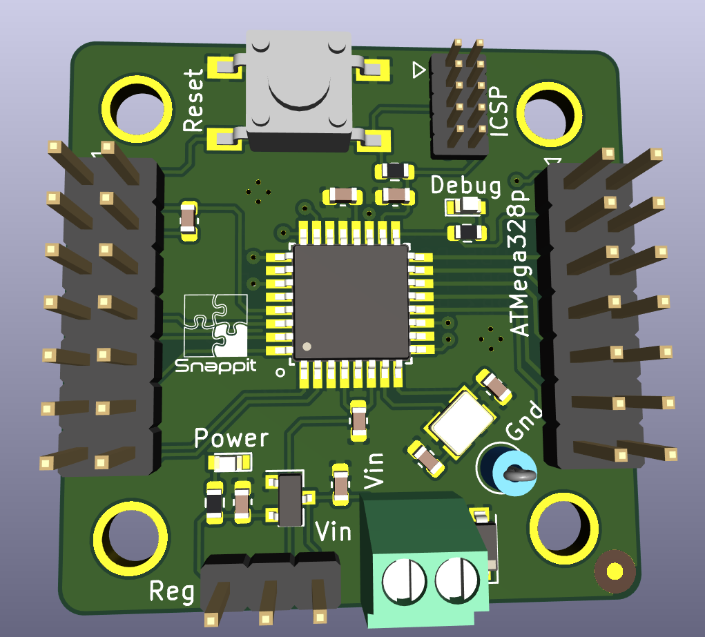
This design measures just 34mm x 34mm and uses four Snappit grid squares. A local power regulator allows the board to be supplied with up to 6v, but it may also be provided with 5v by moving a jumper and changing the voltage from 1.8v to 5v. The fitted crystal must, however, match the voltage.
| Vdd = 5V | 20 MHz |
| Vdd = 3.3V | 10 MHz |
| Vdd = 1.8V | 4 MHz |
Initial bootloader programming is via an external ICSP-connected programmer, with a serial adaptor attached to a few pins serving duty for uploading sketches and viewing debug output. Of course, we are not limited to the Arduino stack if the application requires something else, perhaps with debugger support.
ATMEL AVR ATMEGA2560
The ATMega2560 is the chip that powers the Arduino Mega 2560. It is also still a go-to board for ease of use and learning. As with the ATMega328 board, I removed the extraneous features and expanded the feature set slightly beyond the available stock Arduino Mega.
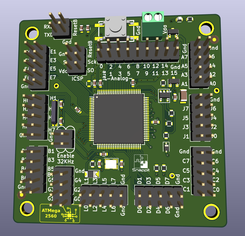
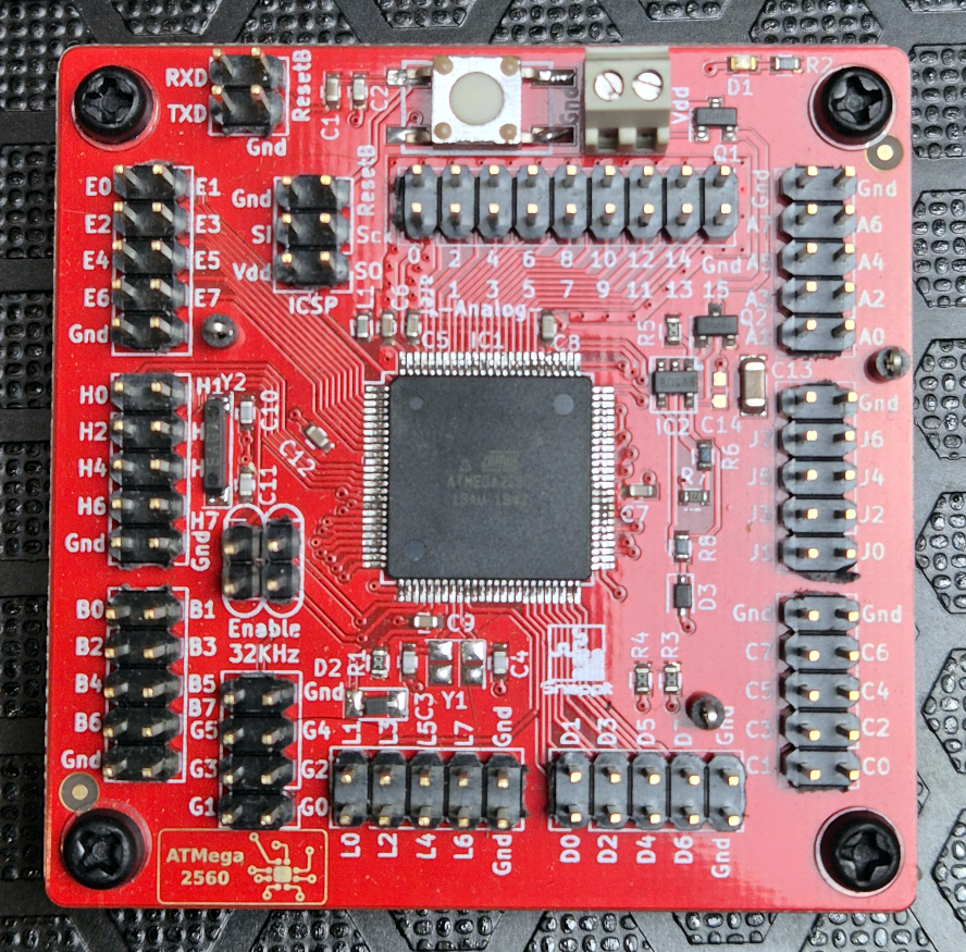
The board is a little larger at 58mm square, occupying sixteen Snappit grid squares. The design is intended to operate at multiple voltages, but performance and crystal frequency depend upon the selected speed grade:
| Device/Grade | Voltage Range | Operating Frequency |
| ATmega2560V | 1.8V – 5.5V | 0 – 2MHz |
| ATmega2560V | 2.7V – 5.5V | 0 – 8MHz |
| ATmega2560 | 4.5V – 5.5V | 0 – 16MHz |
In addition to bringing out all the usual Arduino resources, I added connections for a 32 kHz oscillator for RTC applications.
Microchip MCP7381 LiPo Charger
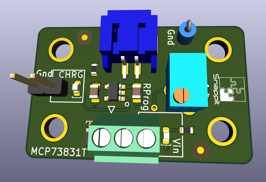
I had a lot of spare MCP7381 ICs in my stock, and it’s a useful device to use when managing single Lithium cells, so it was logical to build a Snappit board around it. This simple board allows the charge current to be fine-tuned to the cell’s requirements—a convenient JST PH-series socket for cells terminated in that connector. If not, the battery can be hardwired with the terminal block at the bottom. The charge status can be seen via an LED or, with a few soldering tweaks, sent to an external device.
SiLabs CP2102 USB-to-Serial
Every Arduino and pretty much every other board like it has some sort of USB-to-serial interface. I’ve stripped that functionality off all my boards and put it on this one. This board breaks out all the CP2102 features while providing some protection during use.
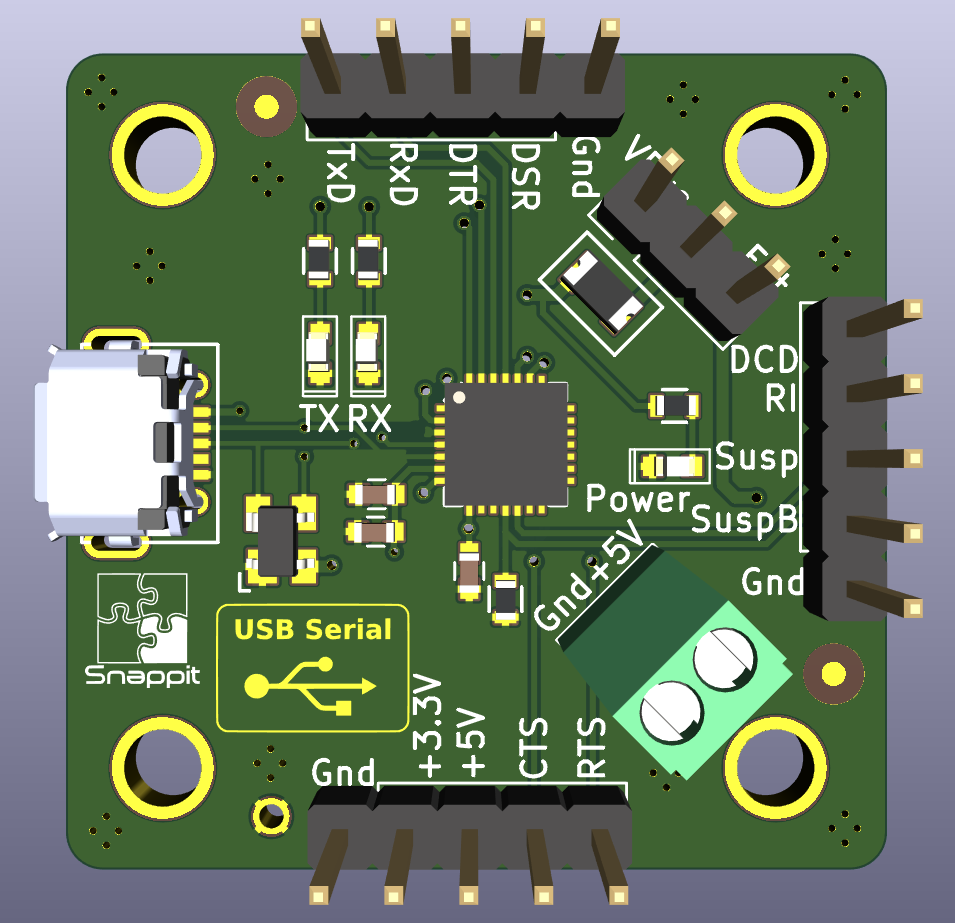
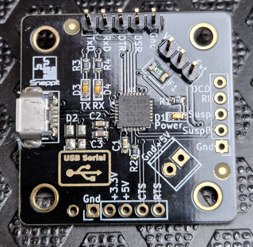
Besides breaking out all the pins, this board allows power to be fed to the device from either the USB VBus or an external pin.
