I enjoy creating various small and large projects, but I often forget to document most of them. This page mainly consists of photos of my current arcade machine build and notes about the components and suppliers. I hope this information will be helpful to someone.
The Concept
The project aimed to create a mid-sized arcade machine with real joysticks, buttons, a bright screen, and a good sound system. I have used the RetroPie distribution for the Raspberry Pi 4 as the software base to support as many retrocomputing architectures as possible. This distribution utilises EmulationStation as the front end and Retroarch as the main backend and supports many others as well. Instead of building the cabinet from scratch, I purchased a pre-cut, 2-UP MDF bartop-sized kit from an eBay seller. If you’re interested, you can find many similar kits by searching for ‘MAME bartop.’
I came across several versions of the ‘bar top’ theme and ultimately chose one made from 18mm MDF coated with a hard, black plastic material. However, I think this was a mistake. When I tried to cut additional holes, the plastic coating was very brittle and splintered badly, requiring a lot of cleanup. Since I planned to cover every surface with self-adhesive vinyl, the plastic coating was unnecessary for my project.
The Display
The bartop cabinet is quite wide internally and nowhere near deep enough to accept a large CRT display, so the only option is a flat-panel LCD. I had the guts of an old 22″ AOC monitor in my stash, which was earmarked for a cyberdeck project that never got going, so I salvaged it and tested it to see if it was still working. Luckily, the display was a perfect fit for the cabinet, and some sort of mount was needed. I decided to 3D print a VESA mount panel with holes that would line up with the slots in the monitor mounting panel. This was then stuck to the rear of the display panel with Gorilla tape. It’s never coming off again! The wing nuts are totally overkill; I just had some in stock.
After installing the display in the cabinet, I covered the visible aluminium edges on the front side with matte black vinyl adhesive slices. These were cut to size using a vinyl cutter and then applied by hand. I then added a sheet of A2 4mm cast acrylic and trimmed it to size using a laser cutter. I intentionally increased the laser power to melt and smooth the edges slightly to give the edges a smoother finish. Ideally, applying some heat from a MAP flame would perfectly melt and smooth the edges.
Check your Materials
I encountered a few issues with my kit. The holes on the top and front panels were all exactly 18mm internal diameter, which made it difficult to fit the arcade buttons that were also exactly 18mm external diameter. To solve this problem, I 3D printed a flat disc of PLA with a guide hole in the centre. I adjusted the print until the disc fit tightly inside the hole and then used an expanding-type hole drill to enlarge the hole diameter to 19mm, allowing the button body to be pushed in and the retaining nut to be tightened. However, the plastic coating turned out to be quite brittle. Additionally, the kit was lifted straight off the CNC machine, so the panels were flat without any jointing allowance. I had to either make a jig and drill it manually or use connector blocks internally. I chose the latter, although it wasn’t the most elegant solution.
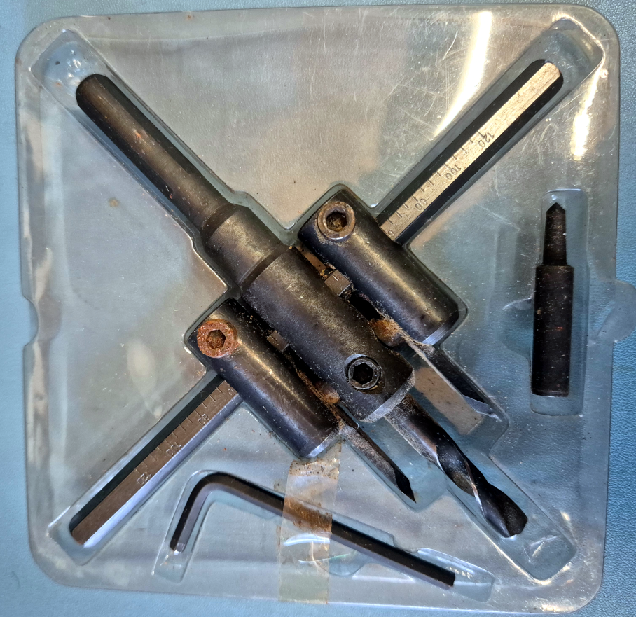
This horrible thing has only been used twice in 20 years, this being the second time. I fully expect there are better tools for enlarging large holes, but I just had this to hand.
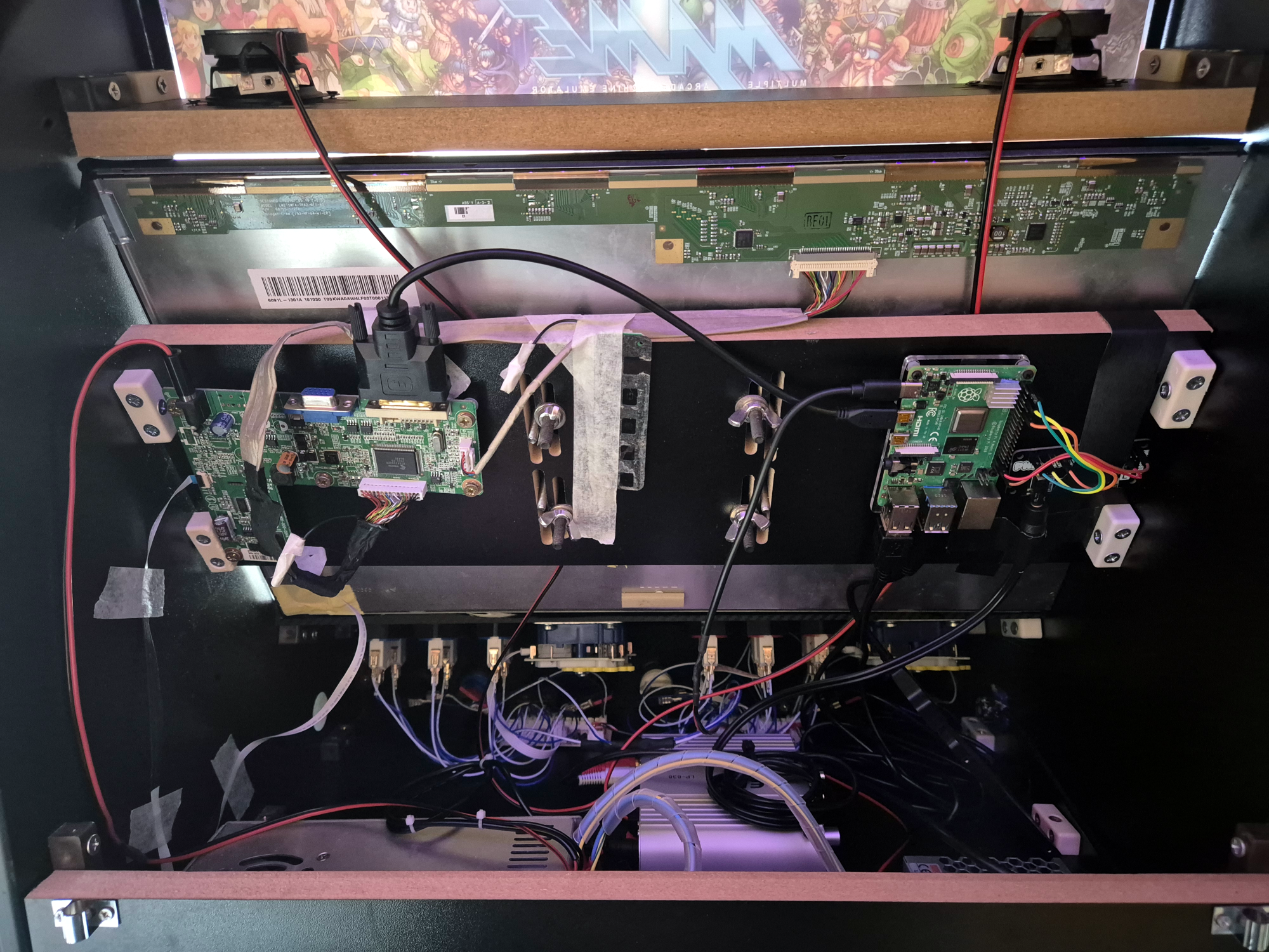
The back part contains the usual mess of wires. I put this together using materials on hand and a few things I bought online. On the left is the display controller taken from the monitor. In the middle is the thin PCB from the base that holds the UI buttons. It just needs to be connected and left as is. I’m using a microUSB-to-DVI cable to connect the monitor because it doesn’t have an HDMI input. On the right side, there’s the RPi4 with an attached Pimoroni pHAT DAC I2S audio board. I added the audio board because I heard constant noise from the RPi audio output. Using the dedicated audio board improved the audio quality. Fortunately, I already had one from a previous project. Since this is a HAT board, I plan to solder a pin socket on it and properly mount it to the RPi at some point.
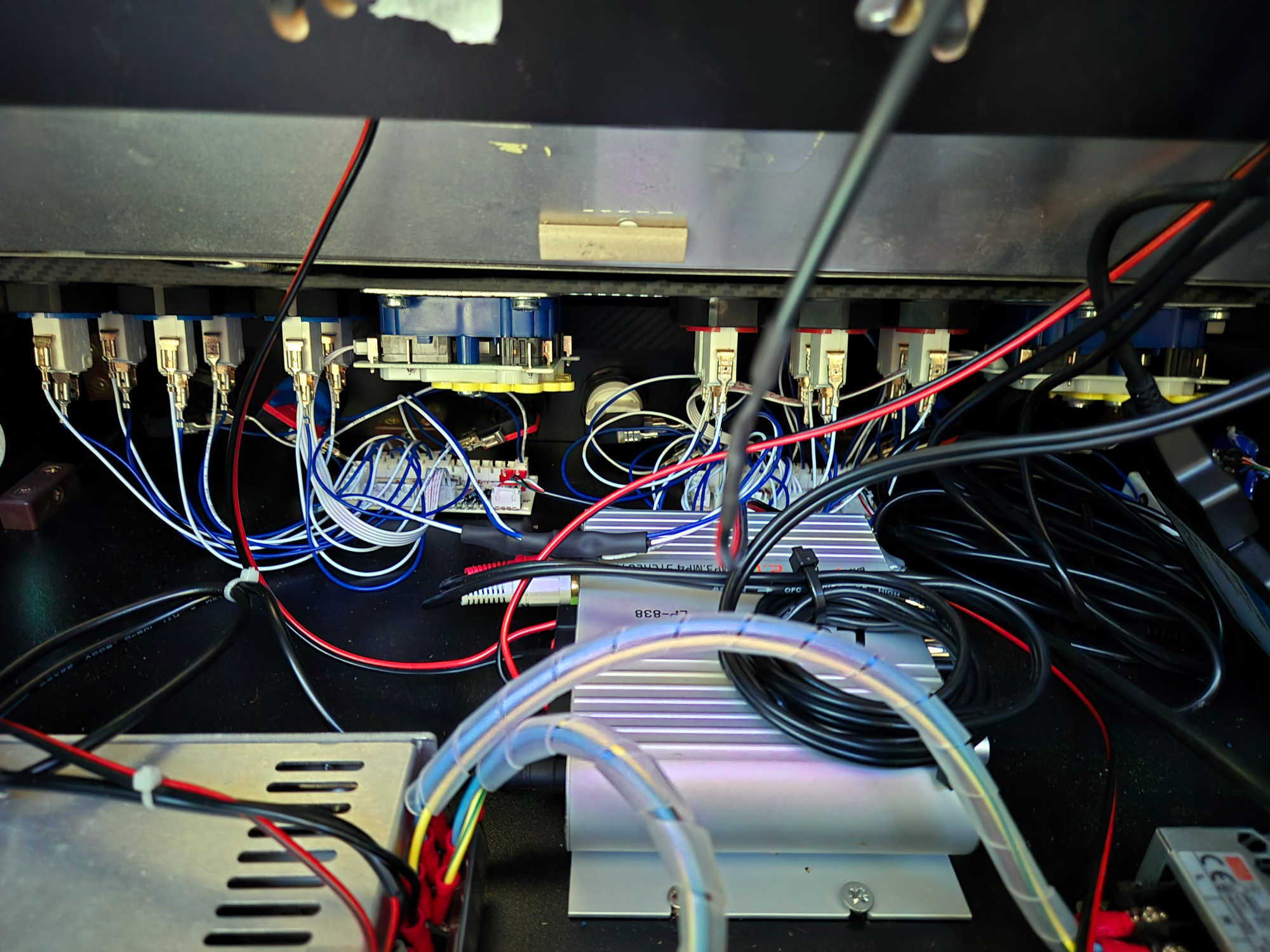
The rear of the top and front panels are visible at the top of the image. These panels are fitted with simple arcade buttons operated by micro switches. It is essential to lubricate the arcade button bodies before installation. It’s difficult to access them once the panel is assembled!
I used two Seimitsu joysticks from the now-defunct ArcadeWorldUK store. In the centre, you can see one of the two gamepad controller PCBs. These PCBs are sold on eBay as ‘zero delay PC to Joystick‘ adaptors. They are recognised as game controllers when connected to the RPi and work seamlessly. I assigned a separate controller for each player while connecting all other push buttons to the player-one board. This made the software setup much simpler.
The audio power amp is also in the centre. This self-contained unit has separate mid-range and sub-woofer outputs. I don’t yet have a woofer to pair it with. It simply connects to the pHAT DAC with a 3.5mm plug.
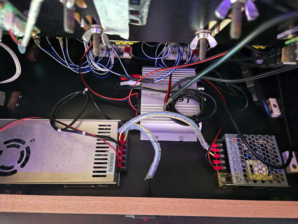
A quick shot of power supplies. These are industrial-grade modular switched-mode power supplies. The left unit provides 12v for the display and audio amp, and the right unit provides 5v to power the RPi4 and the connected USB peripherals. To keep the RPi happy, the 5v supply was cranked up to 5.2v.
The object above the right-hand power supply is a 500GB SATA SSD connected to a USB-to-SATA adaptor. I shouldn’t run out of space on that! I should also mount this better at some point in the future.
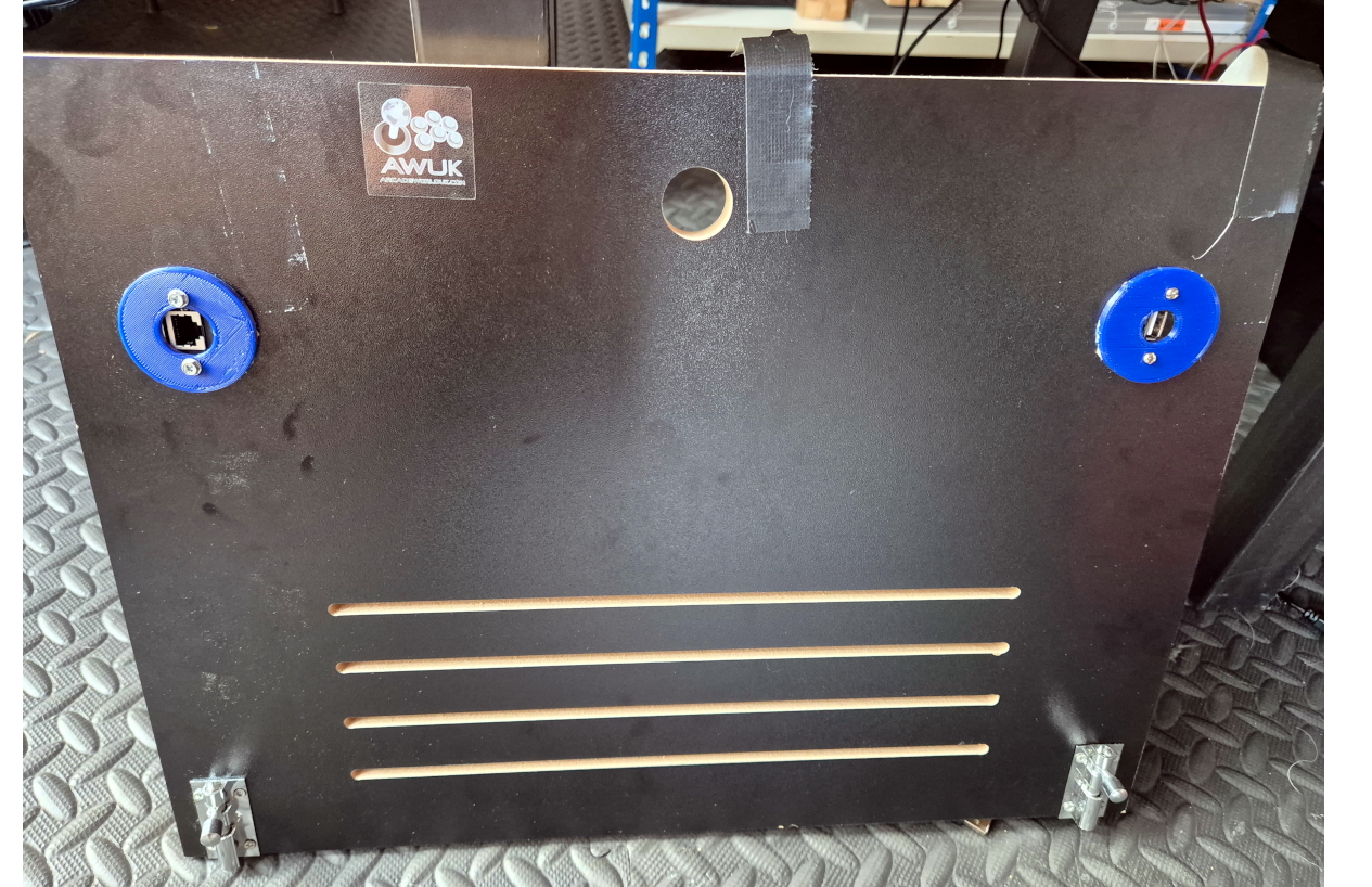
The rear panel is secured at the bottom with slide bolts, but I haven’t found a suitable solution for top mounting yet, so I’m using gaffer tape for now!
The two rear sockets are for Ethernet and USB. These sockets have port replicator cables with the proper plugs. The USB socket was initially meant for an external game controller, but it is currently connected to an external USB hub with a keyboard and a trackpad. One day, I plan to integrate a hub or mount one on the rear and organise the wiring for this setup.
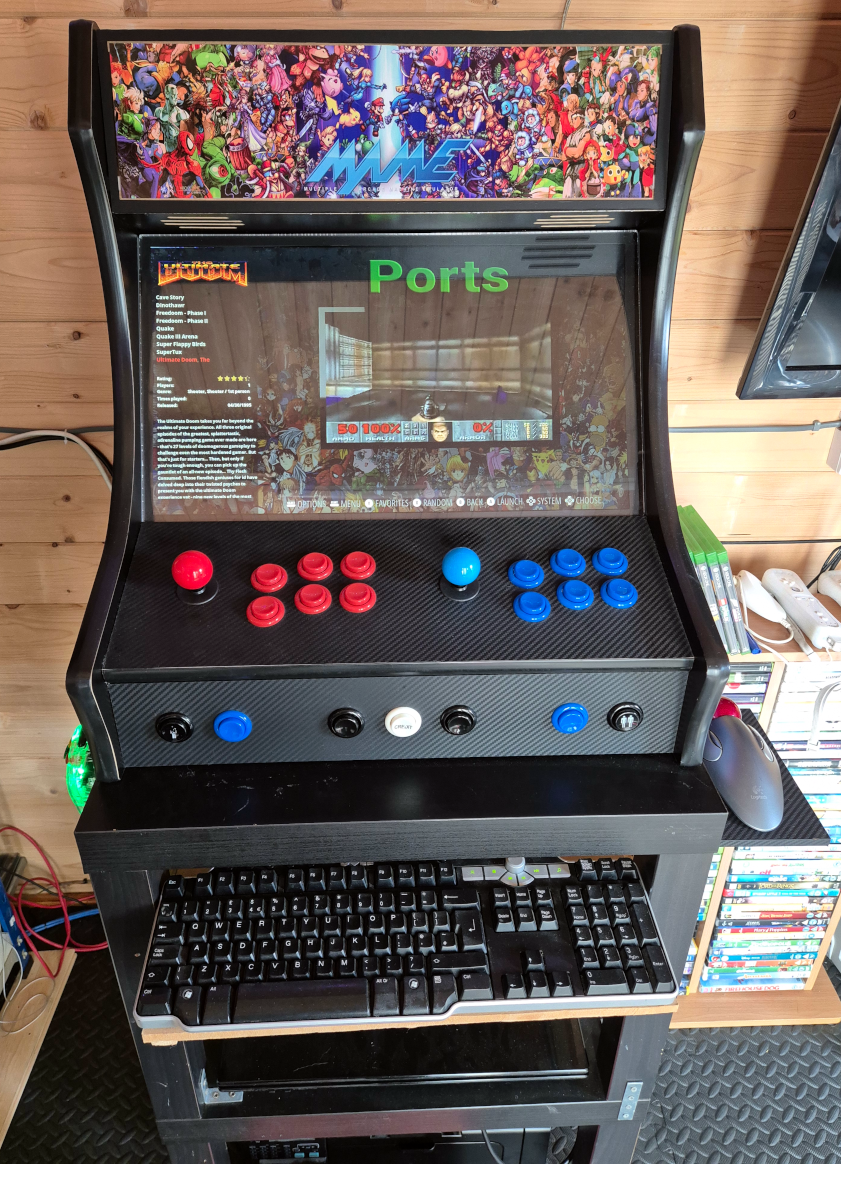
The panels’ edges are designed to stick out slightly forward and are finished with a T-slot groove that can accept a soft plastic T-slot edging strip. Fitting this properly requires some skill—check out tutorials on YouTube!
I used vinyl adhesive stickers from the eBay store RockStar Print for the front and side panel graphics. I applied them using water spray and a squeegee. The top graphic didn’t fully cover the top panel, so I had to add some more matte black vinyl to the edges. It’s not perfect, but I plan to backlight this panel in the future. Also, I need to polish the edges of the plastic cover sheet properly.
I created a stand by screwing two stacked Ikea LACK tables together. The keyboard tray is mounted on drawer runners so it can be slid away when not used. The TrackPoint mount is a straightforward piece of MDF coated in fake carbon-fibre vinyl, which is also used for the control panel surround.
To the left is an Afterglow Xbox 360 aftermarket controller hanging on a 3D-printed mount, which can be found on Thingiverse.
Finally, the laptop on the bottom shelf is used for remote admin access to the machine and also functions as our house’s Minecraft server!
