I needed to study some existing designs to create a miniature airbag for the ABSS project. There are several types of airbag systems on the market that I could explore. Automotive airbags have been available for a long time, so I started by looking at the most mature option. Coincidentally, car airbags are readily available as spare parts on eBay, so I bought a few and waited for them to arrive. In the meantime, I contacted a local car breaker to purchase a steering wheel airbag unit from a crashed vehicle. This allowed me to disassemble it safely without risking any damage.
BMW 3-Series Steering Unit
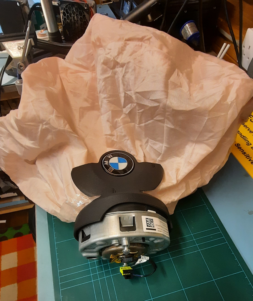
The airbag unit has a steel outer shell that attaches it to the steering unit. The attached centre plastic part is pushed in, and the metal is pushed inwards to grip it. This was a real pain to remove, but it was manageable with an angle grinder.
The housings do not serve any function in the operation of the airbag unit and were discarded after removal.
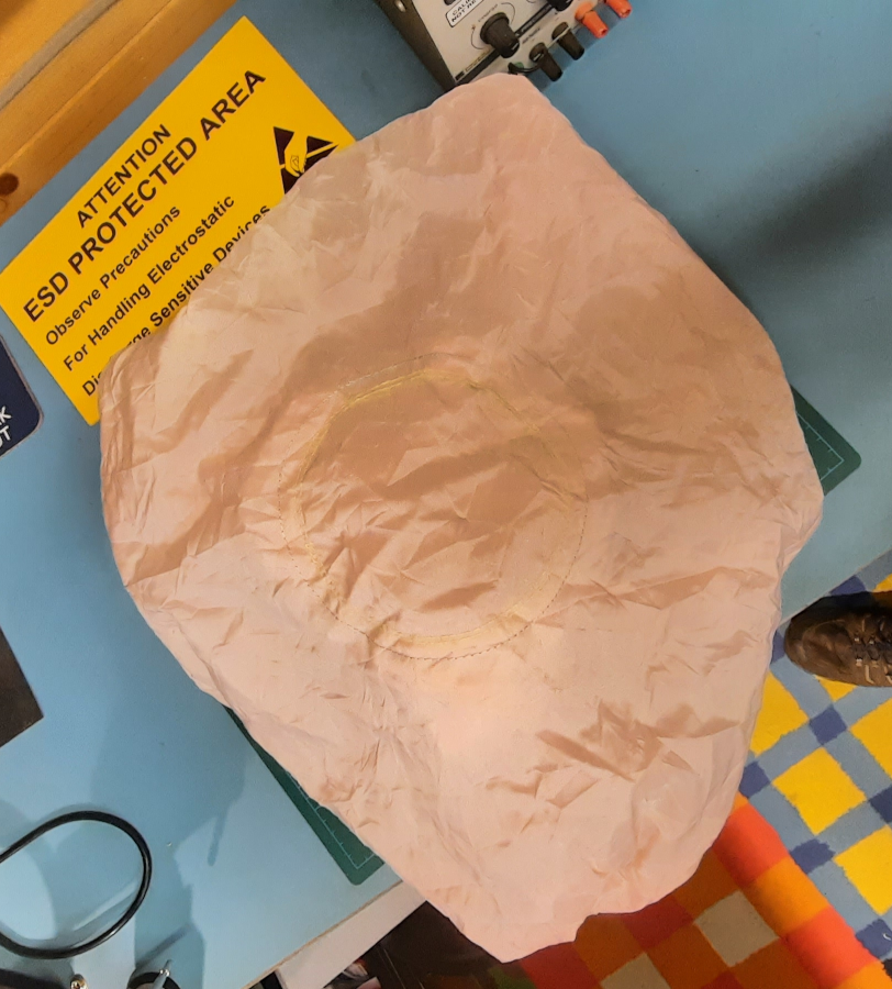
On the top view, the deployed bag has three rings of stitches. Internally, three restraining webs are attached here, which connect to the other side around the gas inlet.
These are designed to prevent the bag from inflating too far toward the driver, creating a shape more like a flattened sphere.
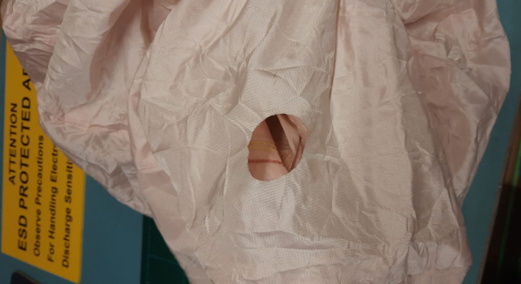
The vent hole is surprisingly large and crucial to ensuring the bag deflates quickly after deployment. This prevents drivers from being pinned into a damaged car. For ABSS, we will also want the bag to deflate, but much more slowly than in an automotive application.
This hole seems to have been cut with a die and is not reinforced. There is minimal risk of widening during deployment.
The BMW Gas Generator
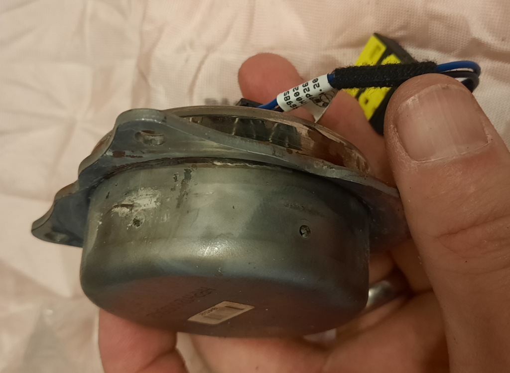
This hefty steel component is the gas generator. It is a typical hot gas generator fitted to most steering wheel airbags. When an electrically actuated squib is triggered, it ignites a booster charge that then sets off the main gas-generating charge in a very rapid sequence.
Inside the bag, metal meshes or bundles of coarse wire filter the gas stream to prevent hot slag from entering or clogging the discharge holes.
The hot gas exits the unit through six small holes. These direct the stream into the deflector/heatsink assembly and then into the airbag.
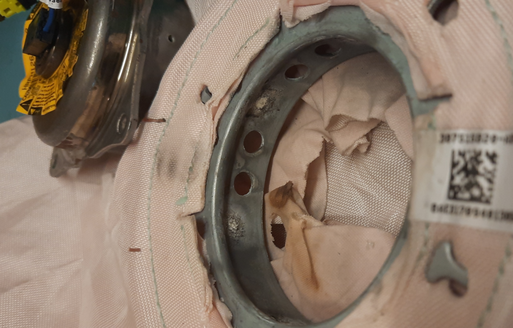
The gas generator is located inside a deflector ring. Its function is to guide the gas in two directions: directly into the bag towards the driver and perpendicularly. This setup ensures uniform and controlled inflation. Furthermore, some of the heat in the gas is transferred to the metal body. This reduces the risk of the bag being ruptured by burning. This also makes the gas safer for the user by lowering its temperature.
You may notice some residue buildup from combustion around the discharge holes on the gas generator module.
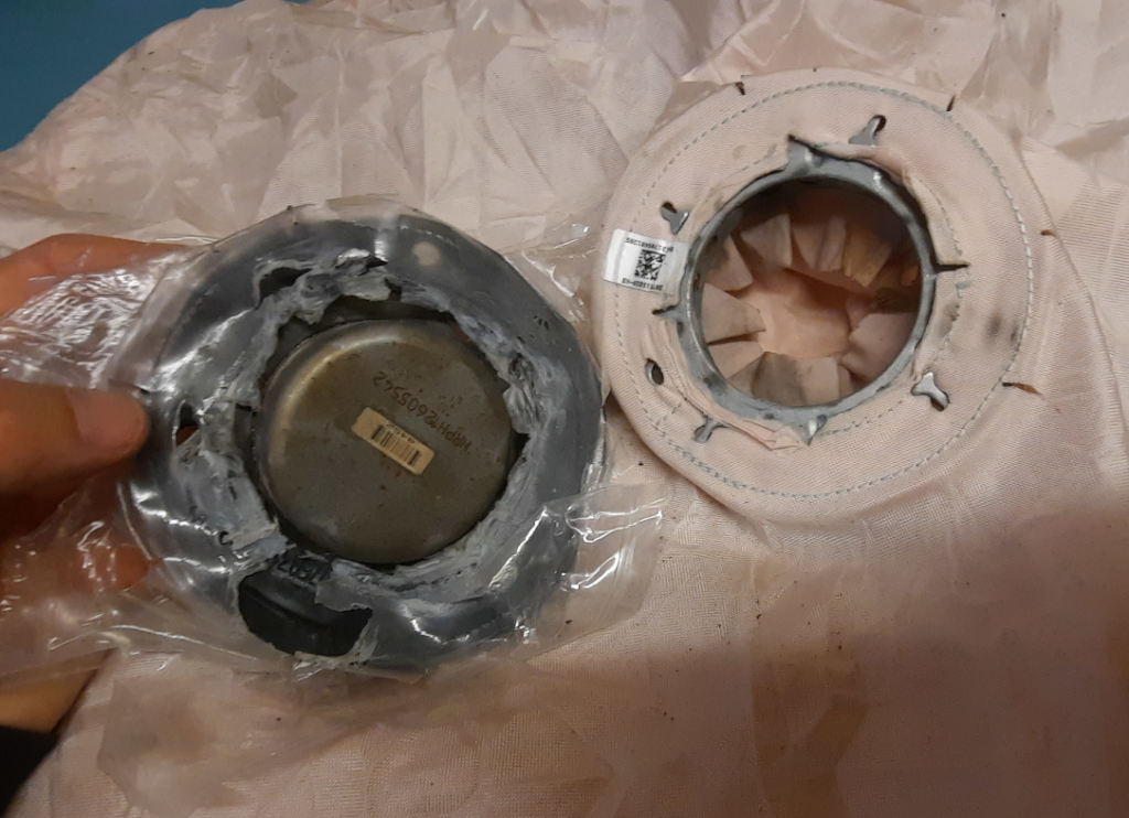
A thin plastic layer separated the gas generator gasket and the bag assembly. This layer appears to be unnecessary. It was probably just the packaging material around the bag when it was shipped to the BMW factory for final assembly.
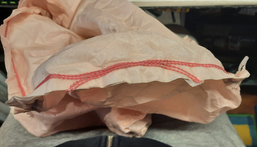
The bags feature interesting stitching patterns. The thread used for stitching is thick and seems to be made of nylon material. It looks like the bags are stitched quickly by a machine. The bags are likely stitched together as multiple units on a panel in one continuous pattern and then cut into separate pieces. The additional stitch lines on the bags may be remnants from entering and leaving this unit during the bulk stitching process.
It is apparent that two thread colours are being used: red and blue. These colours represent the upper and lower threads, which combine to form the stitch. The contrasting colours make it easier to inspect the sewing quality visually. Because of the colour contrast, any irregularities in the thread tension will be easily noticeable. The strength and consistency of the stitch are crucial in this specific application.
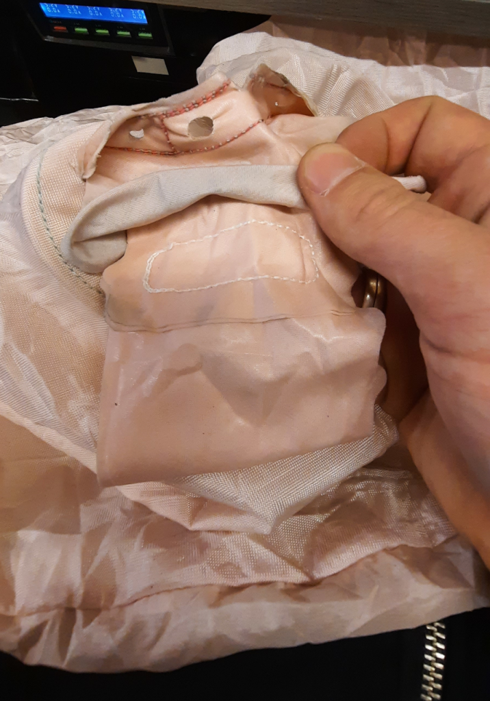
The bag was turned inside out to take this image. The different colours of thread used are noticeable in the picture, which serves as a quality control feature. The white stitching connects one of the internal straps we mentioned earlier. A circular stitch connects the strap to a ring of material stitched around the gas inlet.
Porsche Side Impact
The side impact airbags are slightly different from the steering wheel units. One difference is that they are much larger. Another difference concerns the inflation method. Let’s dig in!
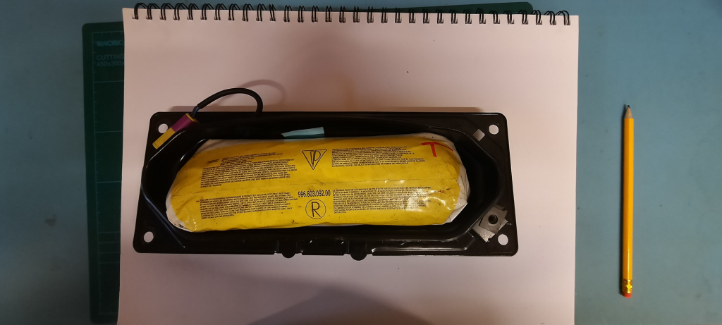
The Porsche side impact bag was neatly wrapped in a plastic bag and screwed to a steel can. This was carefully removed and unravelled to preserve details of how such a large bag can be wrapped tightly yet deploy smoothly. Also, this was a live unit, so extra care was needed. Although handling it unpowered shouldn’t result in surprises, you never know.
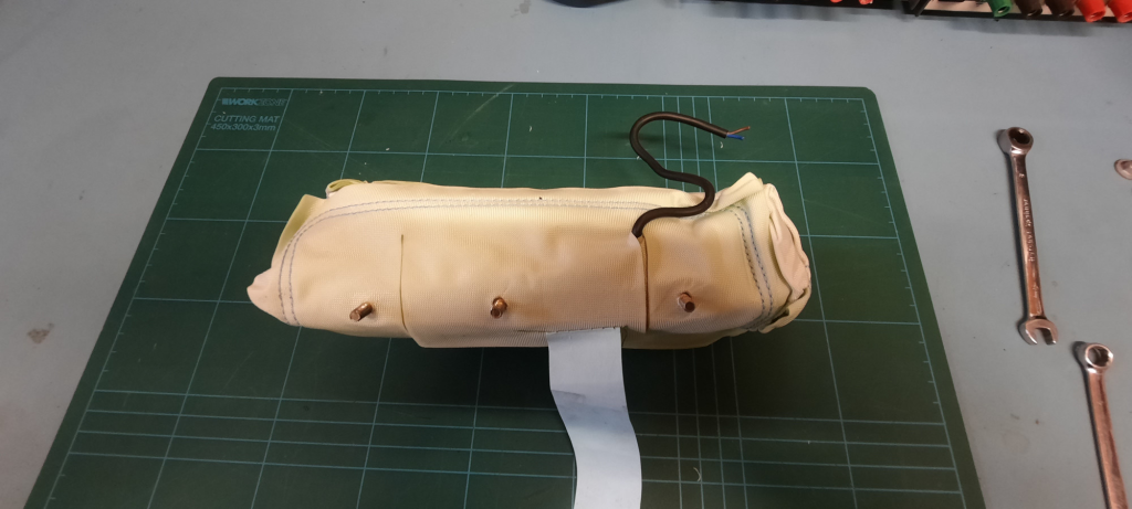
After removing the protective mounting case and the plastic wrapping, I was left with the bare bag unit. The solid-looking studs and the connection wire indicate that the gas generator is fully enclosed and wrapped by the bag. This differs from the BMW bag, where the bag and gas generator are distinctly separate components.
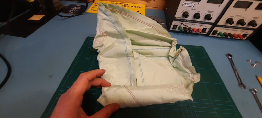
The last part of packing the bag was to roll it up long ways, with a long roll at the bottom and a shorter top section rolled over the top. The mounting studs are at the rear. This is where it is bolted to the door, the bag unfolding away from this direction, into the cabin and towards the occupants.
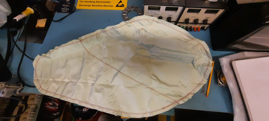
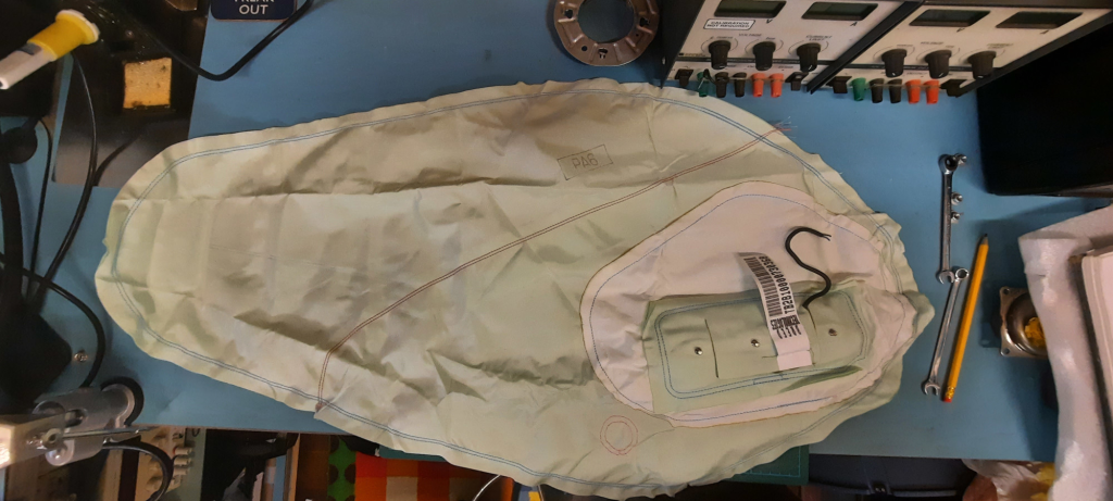
The left image displays the top view of the fully deployed bag. The right image shows the rear view with the mounting section. You can see that the mount within the bag inflates sideways over a considerable distance. The bag’s length is approximately one meter. Clearly visible are three distinct stitched sections that control the direction of inflation and shape the final form. This structure provides valuable insights, which I will explore in detail later.
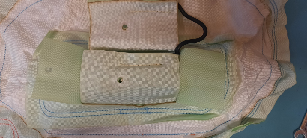
I captured this image as I learned how to remove the gas generator. The photo shows neatly folded layers of material with distinct charring on their edges. These were laser cut, which gives me confidence that I can also laser-cut this material when I make my own bag.
The Porsche Hybrid Gas Generator
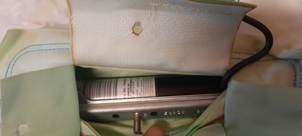
The gas generator was simply slipped inside this pocket, with the studs pushed through matching holes in the material flaps.
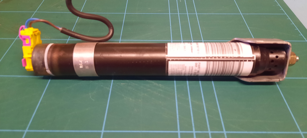
This steel cylinder is a hybrid gas generator containing a small amount of explosive material and highly pressurized gas, likely argon. I handled it with care. Aside from the staggered exhaust holes and the steel gas deflector collar around the end, it’s challenging to determine further details without cutting into them. The safest option is to deploy it first, which I plan to do later when I figure out a safe way to do this.
These devices typically work by electrically initiating a small energetic charge (similar to the BMW device mentioned earlier), which ruptures a small disk that seals the pressure vessel. This causes the pressurized gas to rapidly empty into the bag. The rapidly expanding gas is very cold, so a mix of the hot gas from the energetic compound and the cold expanding gas helps to normalize the temperature a bit. This reduces the likelihood of injuring the vehicle’s occupants.
SMART Side Impact
I just took apart a different type of side-impact airbag, this time from a SMART car. Despite being a small and lightweight car, the airbag unit was surprisingly large and sturdy, especially when compared to the Porsche unit, which was probably designed to be as light as possible.
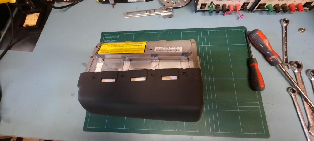
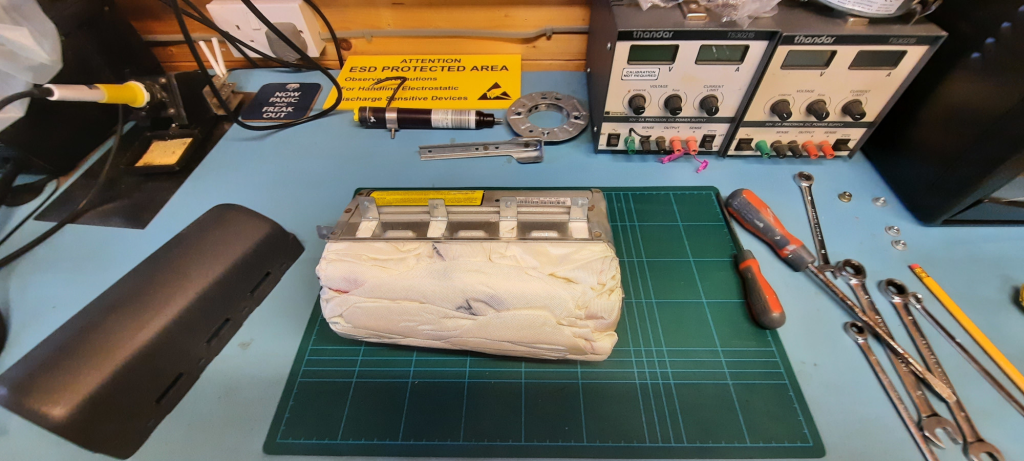
The plastic cover extends into the cabin and covers the airbag. It’s unclear how the cover stays in place during airbag deployment, but we don’t need to worry about that for this project.
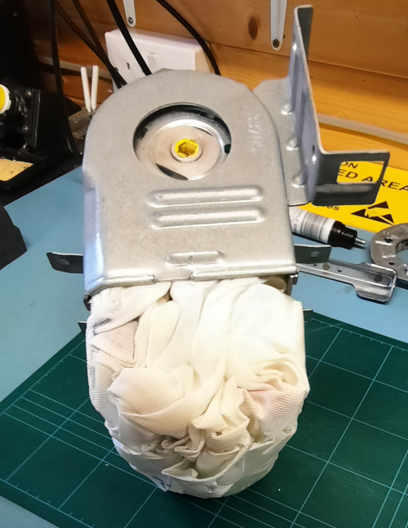
The side view displays the electrical connector to the gas generator and the specifics of how the complete assembly is affixed to the door. Notice the somewhat unstructured, almost ad hoc folding pattern.
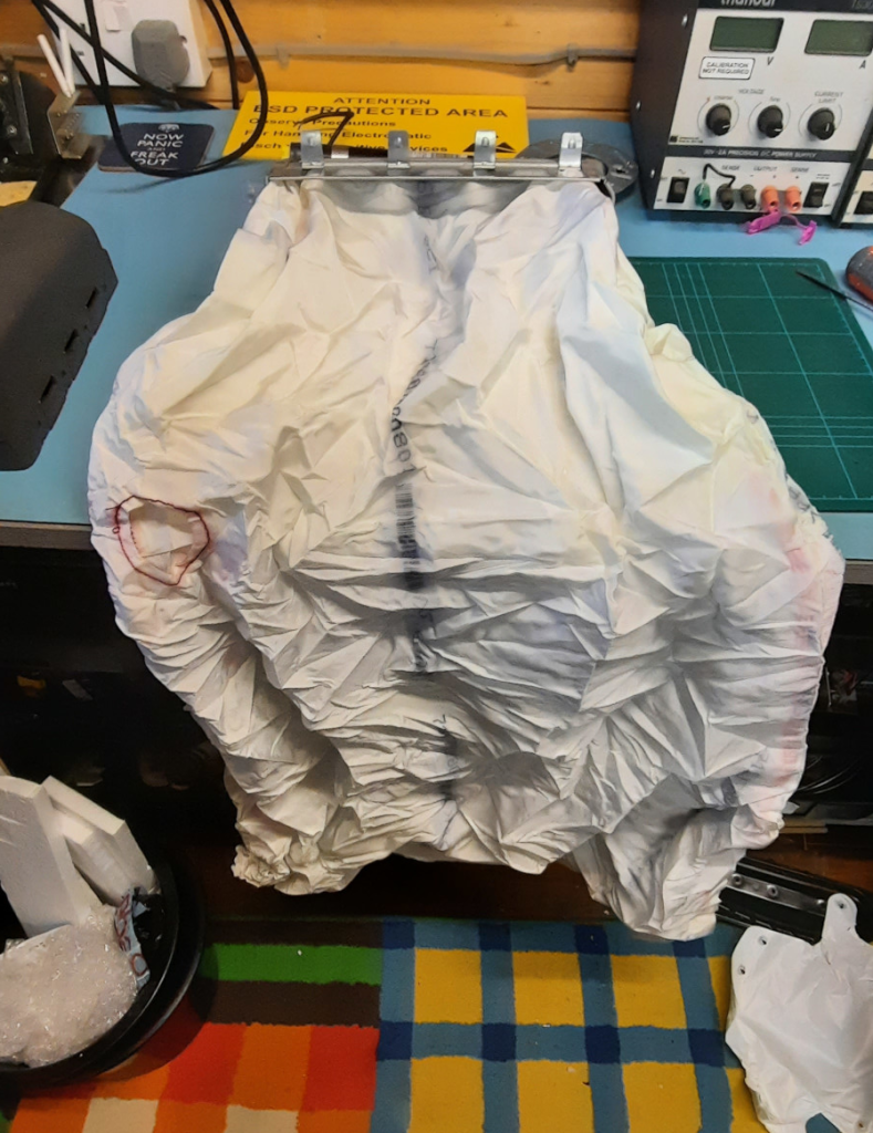
As with the previous side-impact airbag unit, this one is at least 80% larger. In this image, a large vent hole can be seen on the left, which is only single-stitched for reinforcement. The large size of the bag is useful because it provides plenty of extra material that I can use to build my prototype bag. Having a lot of spare material will also be helpful for the learning process, as I anticipate that stitching this will be challenging.
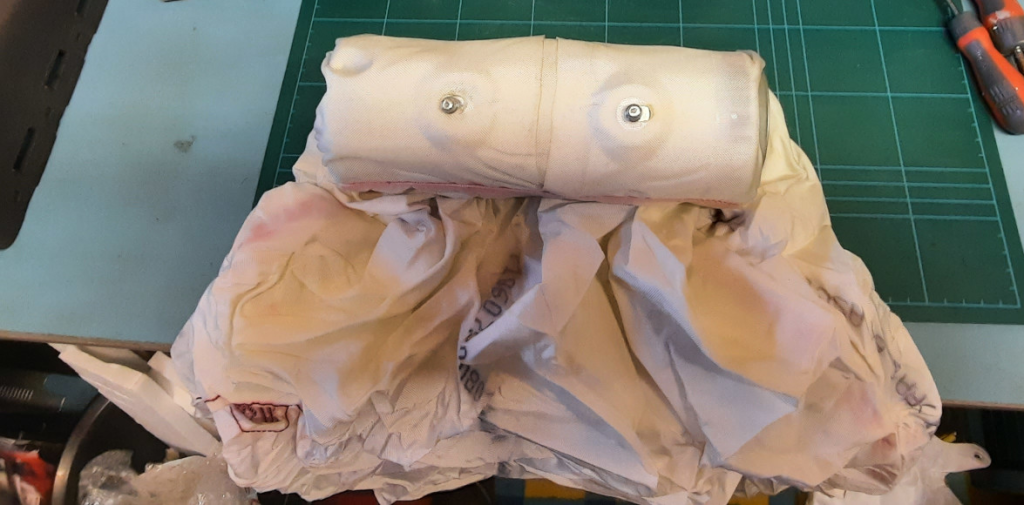
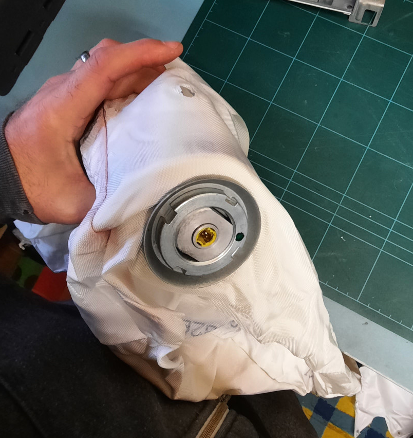
As with the Porsche bag’s construction, the gas generator is fully enclosed by the bag, with the mounting studs passing through holes in several layers of material. However, there is additional hidden metalwork inside.
The SMART Hybrid Gas Generator
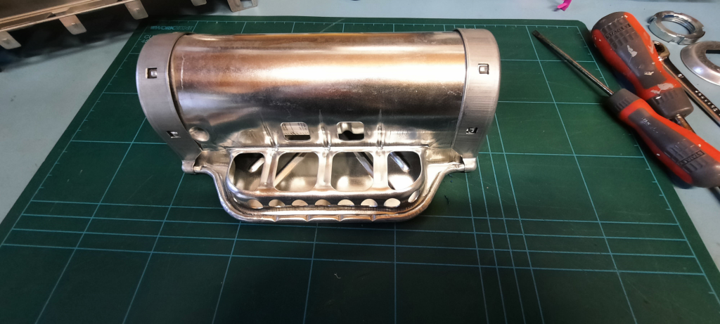
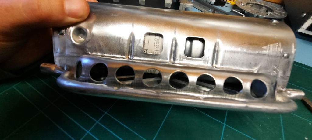
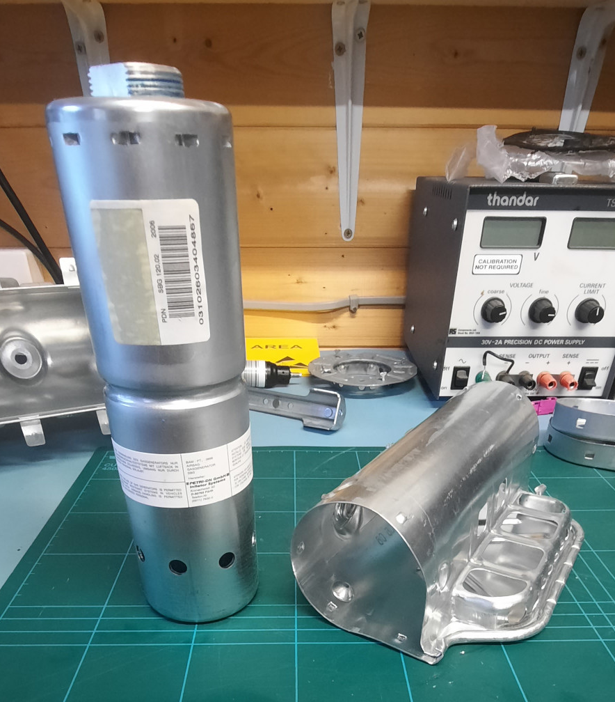
Once you separate the large gas generator from its cover, the construction becomes much more visible. Gas escapes from the holes at one end of the unit. It is then directed against the inner walls of the outer assembly and forced to return to the centre by the end cap that is pressed on. Finally, the gas is directed vertically out of the protrusion at the front.
Modelling the gas dynamics of such a system would be quite a challenge. However, this complexity is likely unnecessary for this project, and we can prototype and test a much simpler inflation path.
Concluding thoughts
Even though I didn’t spend much time on it, the teardown and inspection provided a lot of useful information. There are a few more areas I need to investigate, especially regarding deployment mechanics and how stitching patterns affect the final shape. The placement of internal structures and the control of gas flow are all unknowns and are likely critical for a practical bag design.
