I was running some CAD and simulation jobs on my main machine and was shocked, but then resigned to how much memory was being used without me trying. I wanted to take on some modelling and simulation work for a local client and was thinking of ways to speed things up a bit so that I would not run out of resources. Being a resourceful hacker type (i.e. a massive cheapskate hoarder), I have old computers lying around and piles of parts that could be combined into something useful. I had an old (at least 10 years) HP Proliant DL380-Gen 6 in storage, unloved and unwanted. I had some success in wedging graphics cards into older server machines before, so it seemed like I could do it again.
Let’s get one thing straight right now: server machines and desktop PCS are different animals. These machines are designed to sit in a rack, with only Ethernet connectivity, and are not intended for use as a desktop. They don’t generally have anything but the most basic of graphics outputs, if anything at all. Computer manufacturers are clear about what these machines are designed for; buy a desktop if you want a cheaper consumer machine. If you want more power, buy a workstation. Need a server for your business? Then buy a rack and stuff blades into it. They don’t want you hacking around with the server machines, and certainly don’t go out of their way to make it easy.
Your usual server blade will be sitting there, with its pile of disks running some virtualisation and hosting multiple operating systems, each running whatever server application is needed. I wanted to unlock the whole machine and run it ‘bare metal’ with a single operating system, multiple graphics outputs, and access to all the machine’s resources. Can I do it? Yes, of course, I can. It isn’t that hard.
Issue 1: GPUs
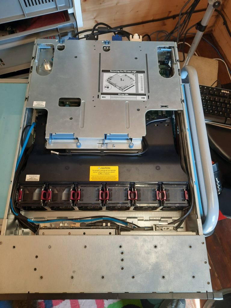
As I said earlier, server machines are not intended for desktop use, so GPU card support is not a priority. The first problems are expandability and physical space. The DL380 uses riser cards for the PCIe. It has two slots on the motherboard, which mate with PCBs attached to the PCI riser cage. This also rotates the orientation of the PCI cards so that they are parallel to the motherboard, allowing the whole unit to have a low profile. Nothing unusual here.
Each riser slot serves a riser card with two PCIe-x8 slots and a single PCIe-x16 slot. There is not a lot of space inside the cage, so a massive GPU card is totally out of the question. But not for just that reason alone. The slots do not provide anywhere near enough power, and the system has no available auxiliary power supplies for a GPU. There is only one solution: finding a GPU that is passively cooled and has a low total power consumption. Finally, there is the issue of cooling. Passively cooling means no fans, so that the GPU core temperature will depend on airflow throughout the case alone.
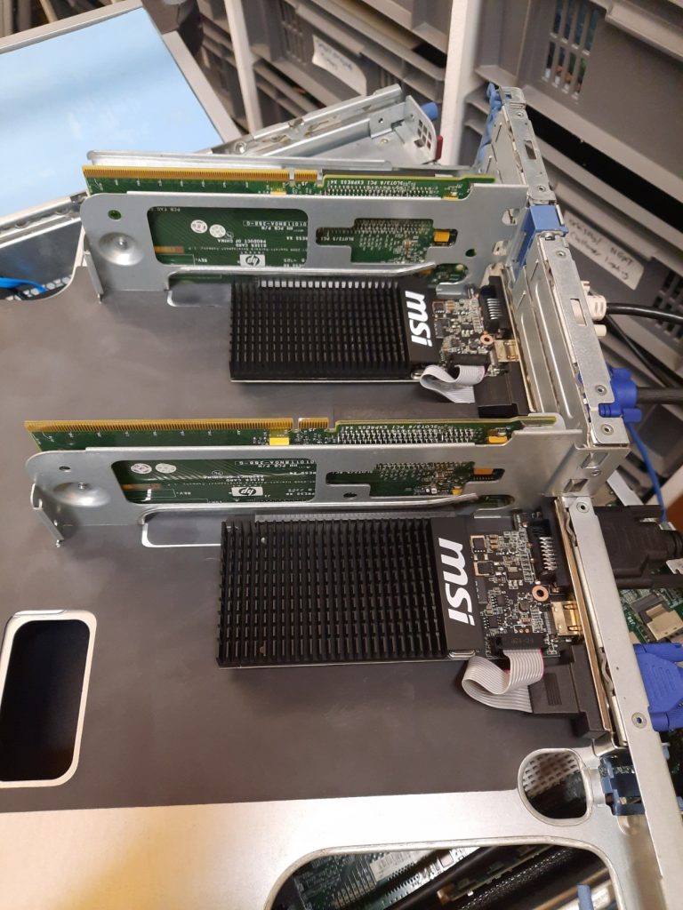
The card selected was an MSI version of the old Nvidia GeForce GT 710 due to its small size, low cost, and meagre 19w TDP. I was confident these would work just fine. However, this card only uses the PCIe-x8 interface despite having a PCIe-x16 width connector, so more bandwidth could be had in the future if I decide to upgrade to something faster.
Finally, there was not enough space on the rear panel openings in the riser cage, so I needed to modify the metalwork slightly. A little filing (OK, a lot of filing) later and the cards fit nicely, so the video cables would actually fully mate, and the cards lock into place.
Once the cards were installed and the system was hooked up to my quad monitor setup, it was time for some testing. That’s when the problems started. First, those six CPU fans spooled up to such an extent that the noise was unbearable. After temporarily ignoring that for a while (I bought better ear defenders), I moved on to the operating system.
I’m a huge Linux fan, having used it since the days of installing Slackware on piles of 3.5″ floppy disks. I tried. I tried really hard, hour after hour, every day for at least a week to get any Linux distro to handle the dual-GPU configuration spread over four displays. After countless hours of research, I concluded that some partly understood bug in X.Org was not being actively worked on, and I abandoned this line of attack. There was only one viable option: to step into the murky world of Microsoft and install Windows 10.
Issue 2: Operating System
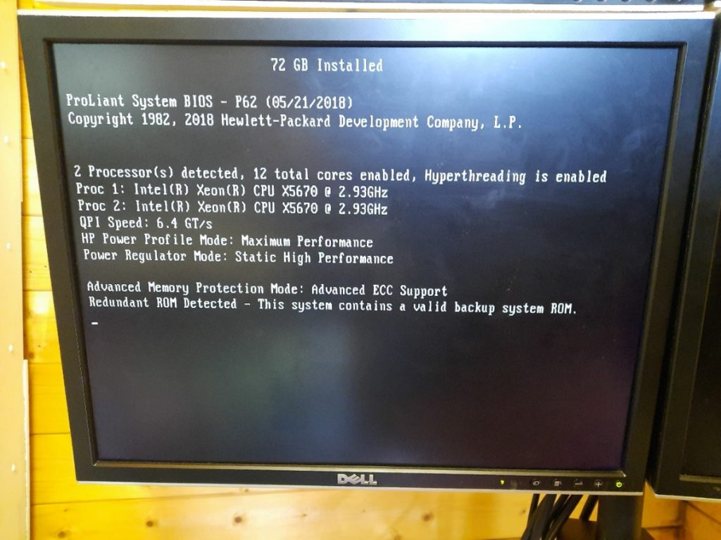
Can you run a desktop operating system on a ten-year-old server, with RAIDed hard disks, two GPUs, and two CPUs and expect it to work without any hassle? Turns out you can! It just worked out of the box; no configuration was necessary. Well, almost. Turns out I bought a Windows 10 Home Edition license, which will only support a single CPU socket. That sucked. So, I bit the bullet and spent more money on a Windows 10 Professional license, which unlocked that second CPU.
Now that the second socket was accessible, I drifted back to eBay, snagged a pair of better processors, and found some clean server-pulled Xeon X5670S. These have six cores running at 2.9 GHz, giving me 12 physical cores (as 24 threads), albeit only DDR3 memory. This is the fastest configuration for this machine, but it is still old. However, it should still be quite capable of simpler workloads.
Issue 3: System Ram
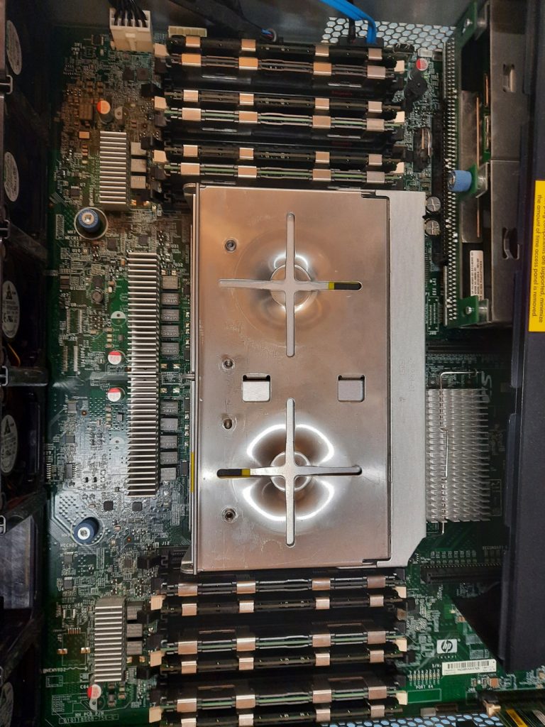
The system RAM is arranged as three banks of three DIMMS per CPU socket, which is 18 slots in total. I wedged in as much RAM as I could lay my hands on, and had no issues getting it all to work. However, looking at the reported memory speed and the system configuration manual, it looks like the system has some bandwidth limitations. The long and short of it is that if you populate all three banks on either CPU, then the DDR3 memory bus speed drops from the maximum 1333 MHz to just 800 MHz, and that won’t do.
So, after sacrificing one slot per bank (i.e. dropping six DIMMS) and using the paired DIMMS in the correct slots, I got it down to the fastest configuration, giving a total of 72 GB of DDR3-1333 RAM. I could have gotten a little more, but I already had spent enough on eBay, and I wasn’t quite done yet.
Issue 4: RAID Controller RAM Backup Battery
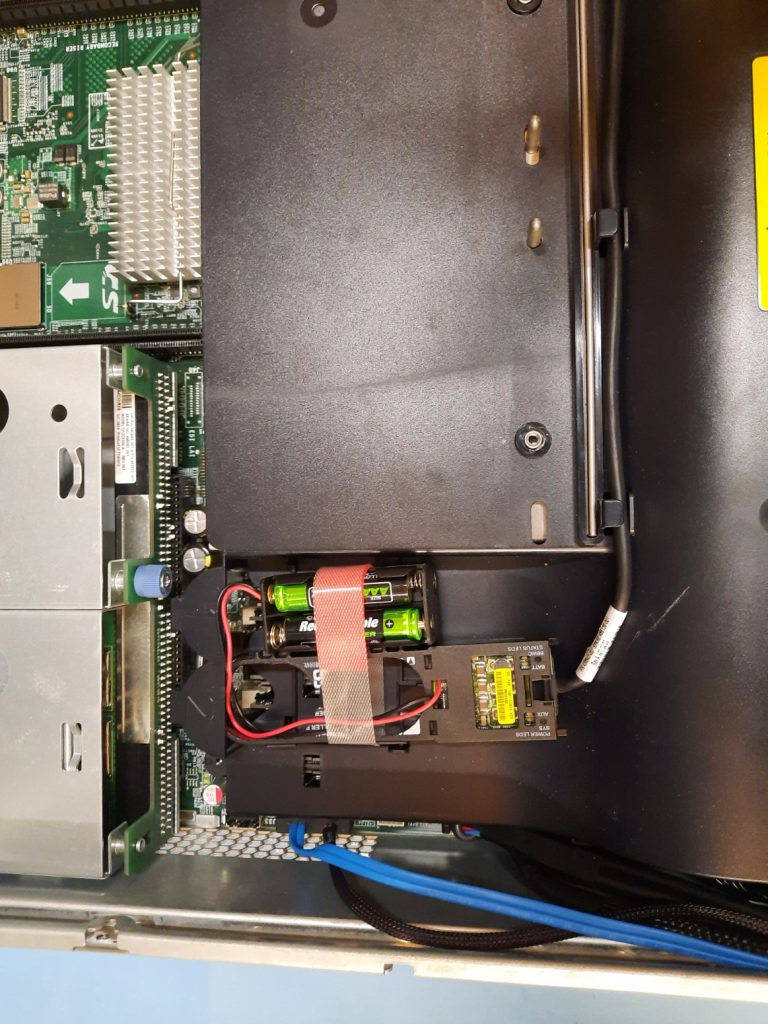
With old machines come annoying niggles. For these Proliant boxes, one thing that fails is the rechargeable battery attached to the P410i RAID accelerator. The SAS drives in the front of the machine are controlled with a dedicated hardware RAID controller, which has either 256 MB or 512 MB of DDR2 RAM-based write-through cache memory. To preserve data integrity, when the operating system shuts down, there is a pause while this RAM buffer is flushed out to the drive array. In the event of a power failure, the cache contents are retained with the help of a rechargeable battery, so upon the next boot, the cache can be flushed and the unwritten data preserved. The battery is separate from the P410i and hangs on the end of a special cable.
This battery module itself is NiMH and does self-discharge over time. The system automatically disables the writeback cache until the battery is fully charged, which can take a few hours. A few hours of degraded performance. Not good. Worse still, the battery fails, and the writeback cache becomes permanently disabled. The solution is either to find a good spare part or, in my case, just rip it out, solder some wires to the contacts, and attach a 4 x AA battery pack. The batteries were charged in a dedicated charger unit before use, so no in-system recharging was needed, and the cache was enabled from boot.
Issue 5: Cooling and Excess Noise
As I mentioned earlier, dropping those GPUs in there really upset something. After a bit of reading, the culprit was the Integrated Lights-Out (iLO) subsystem. These machines have a dedicated subsystem for remote management, complete with its dedicated Ethernet port, which runs on a small microcontroller on the motherboard. The standby power supply powers it, so it’s operational even if the main system is powered off. It is this iLo subsystem that controls the cooling.
When the GPU cards were dropped in, they were not recognised as HP PCI cards, and since the iLo doesn’t know their power profile, it has to assume the worst case and crank up the cooling. It turns out to be a reasonably common issue, and some enterprising hackers have managed to hack the iLo FLASH image to add an additional ‘FAN’ control command, (but that was for the gen8 machine, mine is a much older gen6) to allow it to be manually cranked back down again. But the procedure seemed risky to me, as the iLo has no ROM image backup, so if the update fails or is incompatible with this system somehow, it will brick the machine. I didn’t want to risk it, so I took an alternative approach, which I think will work out better in the end.
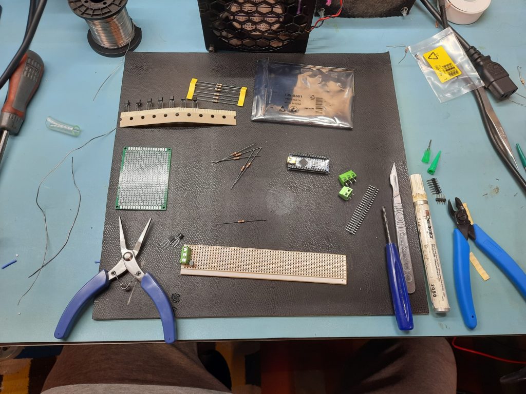
Arduino-Based Cooling Hack: Hardware
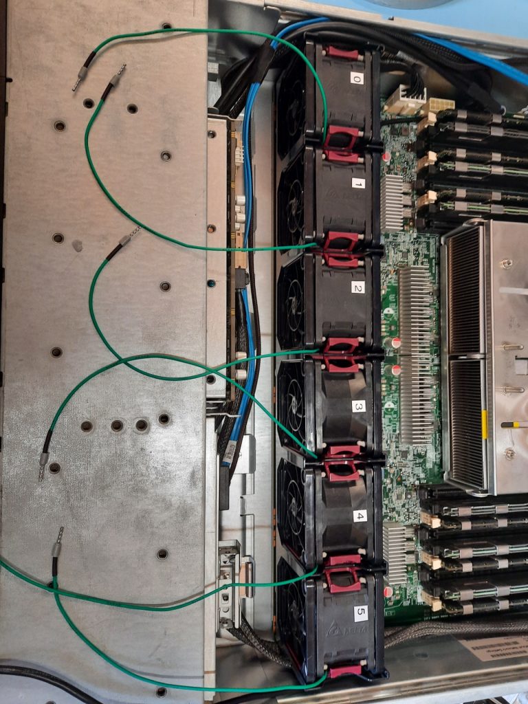
The iLo system controls the six modular cooling fans at the front of the system. Air is drawn in past the drives, then through the huge heatsinks above the CPU sockets and RAM modules simultaneously. Next, the air passes over the motherboard, into the PCI riser cage, and over the GPU card heatsink. Finally, it is exhausted out of the rear of the chassis.
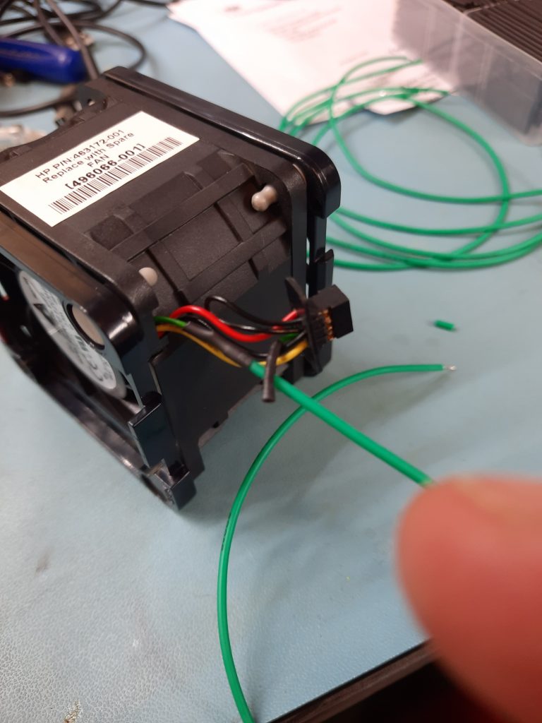
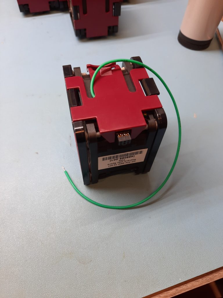
The fans are Delta FFR0612DHE units in a custom plastic enclosure terminated with a plug that allows them to be hot-plugged straight into the motherboard. The iLO controls the fan PWM input, so since we can’t change the firmware to allow fan control via Windows, we have to break into each fan’s PWM signal.
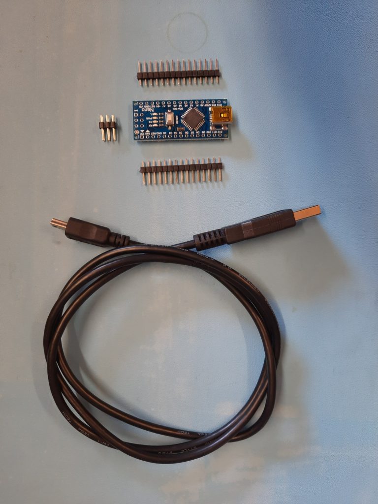
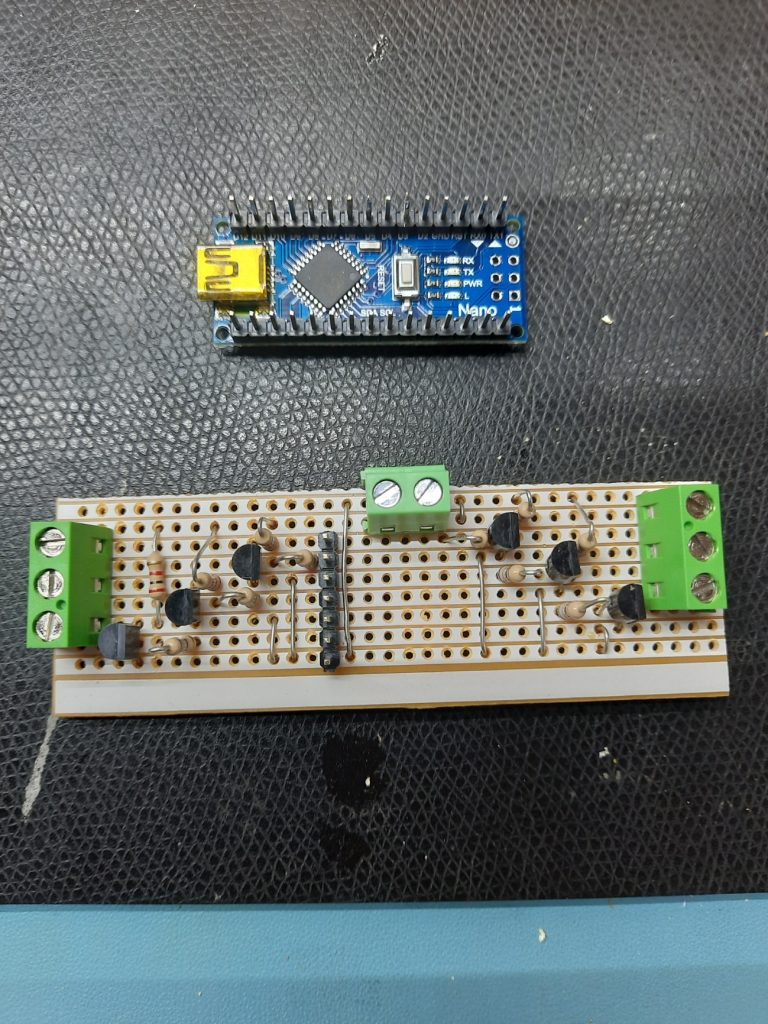
I chose the most straightforward route possible, which was to use an Arduino Nano (clone) I bought especially. The fan PWM input requires a 12V reverse-PWM input, which means that full speed is 0% PWM or tied-to-ground, and zero speed is 100% PWM or tied-to-12V. Since the nano is a 5V unit, we needed a simple circuit with a transistor per fan, to create an open-drain voltage shifter. I just picked some random N-channel MOSFETs and some 10k resistors. You could use practically anything for this.
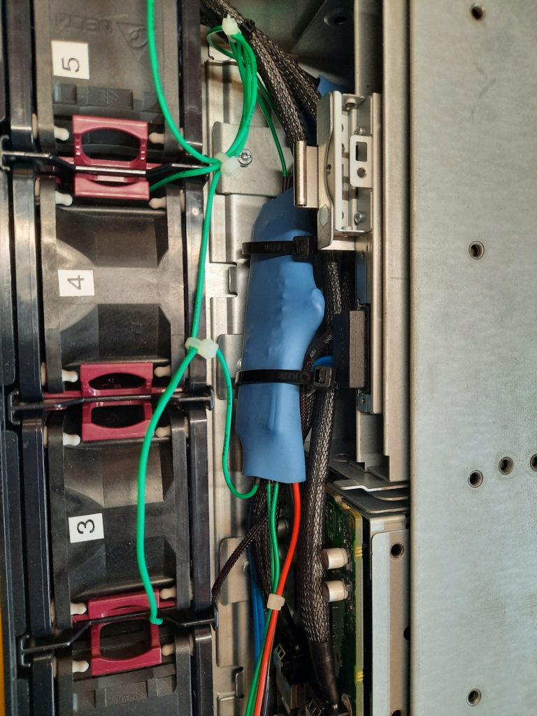
Now that I had made the driver side of things, it was time to hack the fans. It was a straightforward job to break open each fan module, cut off the PWM wire from the connector (leaving enough to reattach if I change my mind), then solder on a length of wire.
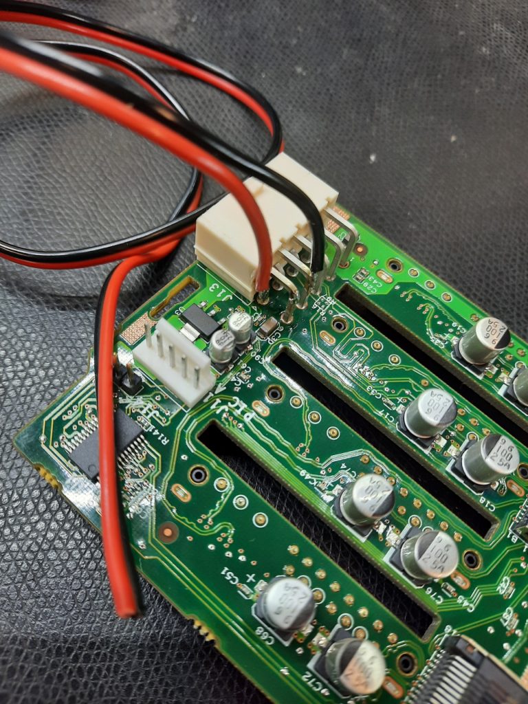
One annoying issue was that I could not find a socketed 12V anywhere, so I needed to tap into the system 12V somewhere to feed that buffer board I made. I did the obvious, tacked some wires onto the back of the SAS backplane, and called it done.
The buffer board was hooked to the PWM signals on the Arduino Nano for a quick test. I wrote a simple sketch that changed the fan speeds one at a time, to prove I hadn’t made any wiring mistakes, then proceeded to install this mess into the rear of the SAS backplane.
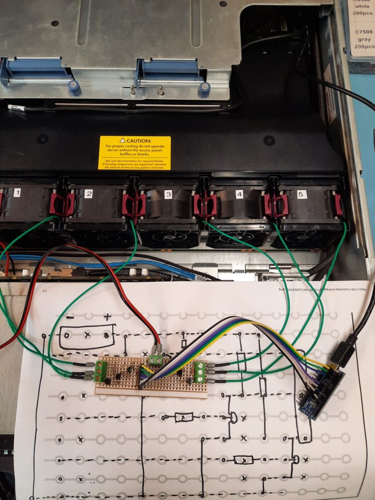
One nice feature of the motherboard was the helpful internal USB socket, just behind the far-left end of the backplane. This was perfect for powering and controlling the Nano. A little heat-shrink and tie-wrapping later, the circuits were squirrelled away somewhere they would not cause too many problems.
Arduino-Based Cooling Hack: Software
The first things to think about were failure modes. I wanted to have a split software package with simple, dumb firmware on the Arduino, and all the smarts on the PC side. The communications between the two were via an emulated serial port that you get for free with the Arduino stack. The idea was that the Arduino firmware would simply sit there waiting for fan control commands, programming the PWM outputs as appropriate when a change was noted. I noted that the first failure mode would be due to failed communications to the Arduino, so the default behaviour was to sit in an infinite loop, expecting six fan control values, and updating the hardware each time. If a suitably small timeout expires, all fans would ramp immediately to 50%.
The initial fan control rate was 100% for a few seconds to ‘blow out’ any accumulated dust and spiders. Then, it settled down to 50% until the operating system booted and the other end of the link was established.
On the host side, an initial testing Python script looks like this:
This is about as simple as it can get, and still allows some configurability for the project’s testing phase.
Next Phase
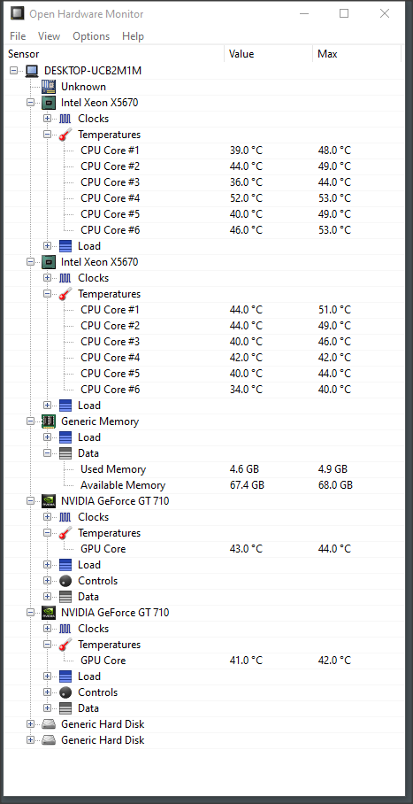
The next part of the project will concentrate on the software side of things. I am monitoring the machine visually with Open Hardware Monitor, which allows me to read all the system sensors correctly. Also, the Windows DLL is designed to be used with other software. This will allow me to write my own fan control client, which monitors all the temperatures, fan speeds, and system load to correctly pre-empt an increased CPU/GPU thermal load and ramp up the fans to an appropriate level in a smooth and minimal fashion.
It would be trivial to just use the core temperatures and have a PID controller compute the fan values, but I feel it would be better to predict the temperature rise rather than react to it after the fact. This should result in fewer temperature fluctuations and fewer annoying fan ramps.
I plan to program this in Rust, as it is the perfect project to test the DLL integration and will be my first graphical Rust application for Windows. I have quite a lot to learn to achieve this, so watch this space for updates in the coming weeks (or, more likely, months!).