
When working from a small space, it’s always a challenge to make the best use of every inch of it. During lockdown in the middle of 2020, I decided to gut my whole workshop and store everything in my second shop. I took lots of measurements and started to sketch out ideas to best make use of the space.
The first issue was with space for storing small parts and evaluation boards, and how to keep the parts for various projects together.
The second issue was with recall—how do I locate a part, project, or tool when I stow it away?
Plastics
A friend from my local hackerspace gave me a huge pile of Euro-stacking containers, similar to these:
These were the standard 600x400mm footprint kind, in various heights.
I had three sizes, mostly the small kind, which were about 73mm high, a fair few of the bigger 150mm high type, and a handful of the 120mm high kind.
I devised a simple arrangement (using Inkscape!) to fit as many as possible in my available space.
Computer stuff
I’ve had a few 19″ racks over the years and recently got rid of the last one, as it was just not very space-efficient. I like mounting kit this way, as it’s very tidy and sturdy. I decided that this storage rack could encompass a 19″ section too, and that would take care of a lot of my storage issues.
On eBay, rack rail kits are available for very little outlay, so I ordered a couple that were about the right length and designed around them:
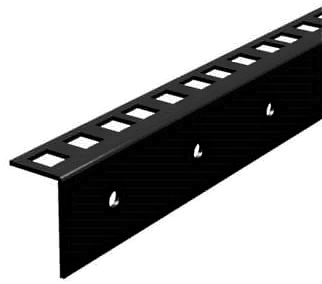
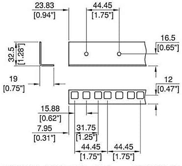
This part is available from Amazon
Available Space
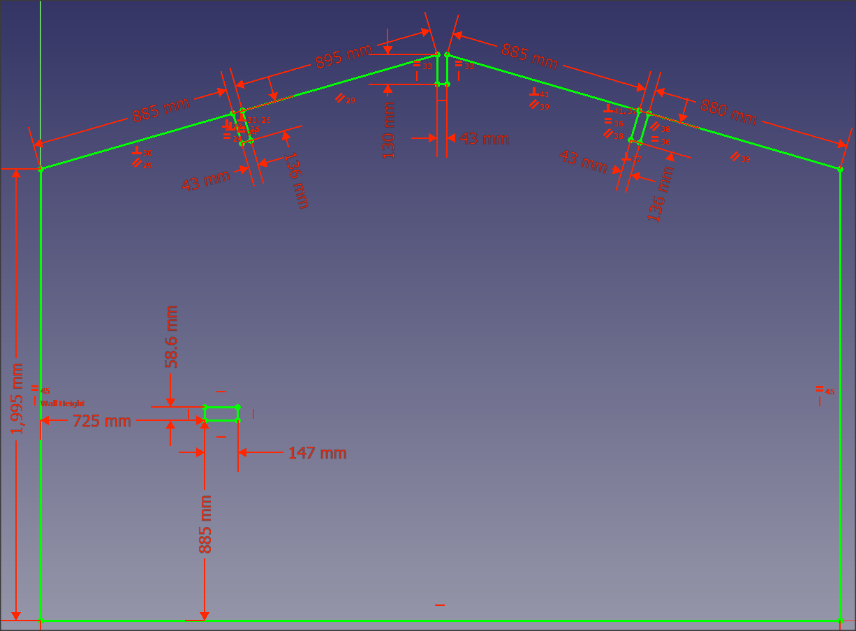
I started measuring the internal space’s rear wall and sketched it in FreeCAD. I would design the whole thing in CAD and break the assembly apart to get the sheet sizes and drill locations. Then I got impatient and just sketched it manually instead. This sketch was my reference to ensure it would fit when assembled.
I made a mental note to ensure that there was enough floor space to assemble it, that the sheets would fit through the door, and that if I assembled it face-down, I could actually erect it without fouling any of the timbers inside the space.
The Design
The design is a very simple box. It is internally divided into five columns, the leftmost of which is set up so that the internal size, taking into account the rail kit, gives the correct 19″ horizontal hole-to-hole space needed for the rack-mounted kit.
The remaining space is divided into four equal-width columns, with an internal space of 410mm. The boxes are fitted so they protrude 600mm away from the rear wall, and 400mm wide.
The extra 10mm gives 5mm clearance per side.
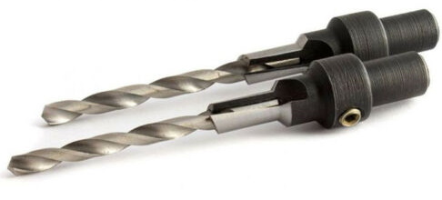
To keep costs to a minimum, I decided to use the cheapest, sturdiest material that was up to the job – an 18mm MDF sheet. Butt-jointing, wood glue, and 7x50mm confirmat screws to care of the construction. EBay supplied these, together with the matching drill. This also handily drills out the wider section for the shoulder of the bolt to drop into, as well as countersinking at the same time. Easy!

These were provided by eBay seller peter-diy. Go check out his store.
The rails were held on with some M4 x 30mm button head Allen bolts:

These were provided by eBay seller boltbase. Go check out his store.
First Pass Layout

After making more detailed calculations, I determined that I needed to spin the trays 90 degrees and align them so they are narrow-side on, making each column 400mm + clearance in width.
Once the 19″ rack section was added, and considering the 18mm uprights, plus clearances, the total length of the top/bottom sheets exceeded 2400mm.
Since that’s the standard sheet size available, and about the limit I can fit in my car, I needed to compress it horizontally to fit. Annoyingly, I needed to sacrifice floor space in front of the rack. It was only 200mm, but every little helps in a small space.
The second issue was vertical clearance. After allowing for some vertical tray float, for assembly, any wood expansion (unlikely for MDF, mind), and inaccuracies in drilling and wood thickness, it looked just a little too tight. The only option was to lose a row of the small trays from the top. So it became a 4×8 array, not 4×9. Which sucked a little, but it was still massive 🙂
Support batons
I had some good-quality pine left over from building a second workshop, so I cut it into batons to support the drawer units at each side. This required lots of drilling, gluing, and screwing, but that cost nothing but time, as I had everything to hand.
The final tray count was 4 columns x 15 rows, or 60 trays. Two batons supported the trays, which made 120. It took quite a while.
I made the batons 18mm high, 20mm wide, and about 580mm long (limited by the wood I had to hand) The trays have little shoulders on the bottom, which needed to line up with the batons, but that was just a matter of making the spacing correct to not foul.
Each baton had four holes drilled and countersunk. The idea was to never screw into the MDF (shown in black below), only the solid pine baton (shown clear below).
Some short screws (Blue) were located to give a decent amount of purchase on the 20mm wide baton, once 18mm of MDF was penetrated. These served as the batons at either end of each row.

Longer screws were needed for batons screwed through the three inner supports, this time the screw needed to pass through one 20mm baton, 18mm of MDF, and still have a decent amount of purchase on the opposite baton.
Pre-drilling
It was very important to pre-drill the holes in the sheets and batons to match. I made a simple sliding jig from a spare sheet and some metal offcuts.
The jig was arranged to have four holes near one end and to slide parallel over a sheet.
A few metal plates were added at the edges to prevent sideways slip and rotation.
With the first sheet marked up with the correct baton centres (i.e. where I wanted to drill the holes), I could slide the jig to the next baton location, drill four holes and repeat.
Once the first sheet was fully drilled and checked, it was simple to clamp the other sheets to it, using it as a massive drill jig.
This made it possible to replicate the hole pattern accurately enough.
Once all the sheets were drilled, the drill jig was modified to hold batons appropriately so they could also be pre-drilled.
This took quite some time due to the quantity involved and the need to countersink the baton holes as well.
Final Layout
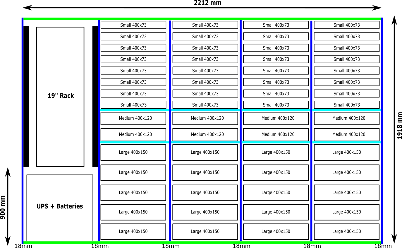
The final layout shows how the sheets fit together. Green is the longest at 2212 x 600mm and forms the top and bottom. The bottom sheet bears all the weight of the structure and contents in compression, so this is fine.
Dark blue is the vertical sheet that bears the distributed weight of the contents, again in compression. For ease of assembly, the inner sheets sat directly on the bottom, with the end sheets sitting on the floor.
These end sheets were secured to the top and bottom sheets with four confirmat screws at each end, into the end of the corresponding top/bottom sheet.
The inner sheets were secured top and bottom, again with four confirmat screws at each end.
Finally, a single 2400 x 1200mm sheet of OSB counteracted any tendency for the structure to move out of square.
The sheet was divided into three long strips, approximately 2212 x 400mm, and screwed into the back of the rack, spanning all the uprights. The top and bottom OSB sheets were overlapped with the top and bottom sheets and screwed into them.

Before drilling the OSB sheets, the structure was trued by measuring the diagonals and pushing the bottom sheet sideways to equalise.
Once trued, the OSB sheets were clamped and drilled into the end of the structure to prepare for gluing and screwing.
All wood joints were glued before the final screwing.
Final Touches
After leaving overnight for the glue to dry, the batons were fitted, again with much glue and lots of screws. When that had a chance to dry off, paint was applied.
First, a coat of watered-down junk emulsion to prime and seal the surface, followed by a couple of coats of boring old white.
Accessorise
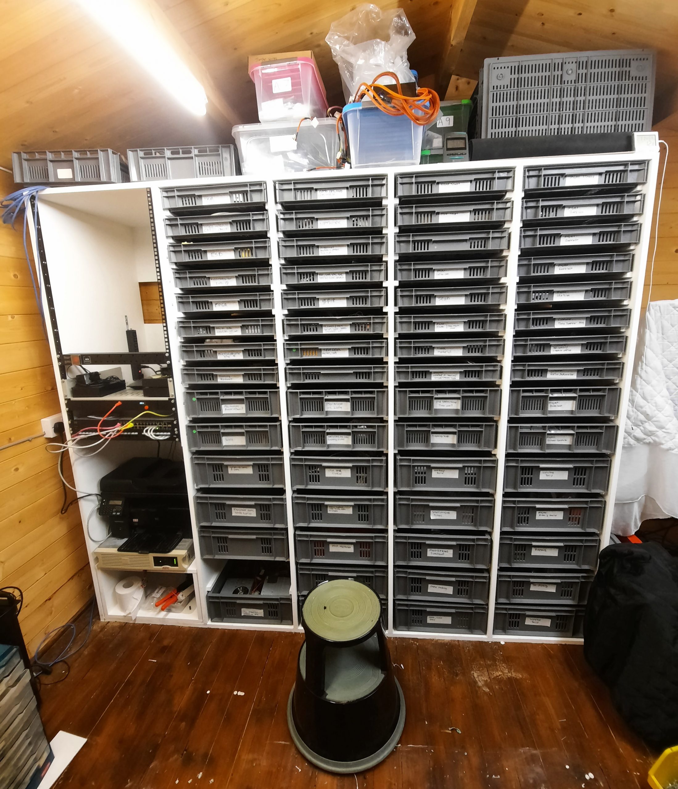
The reason for the 900mm rack height in the final layout, is to allow a workbench to butt up against the rack, with the surface of the bench lining up with the bottom of the rack. This allows me to add rack-mounted electronics equipment, such as power supplies or anything else I decide to build. With the bench in place, the ugly UPS is below it, out of sight, doing its thing. Above the bench, everything is accessible from anything on the bench.
Currently, there is a Cisco managed switch and my recent cheapo NAS build in place.
I added a shelf I had lying around to park external USB drives and a rack-mounted power distribution unit.
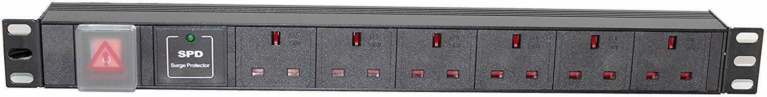
This was supplied by eBay seller kaza-uk and was surprisingly good quality for the price.
One wouldn’t usually put such a thing in a rack, but since it will be very close to my bench, it was appropriate to supply power at this location.
I’m sure this project will develop further over time, but this is as much as I need to do for now – other builds are in progress!