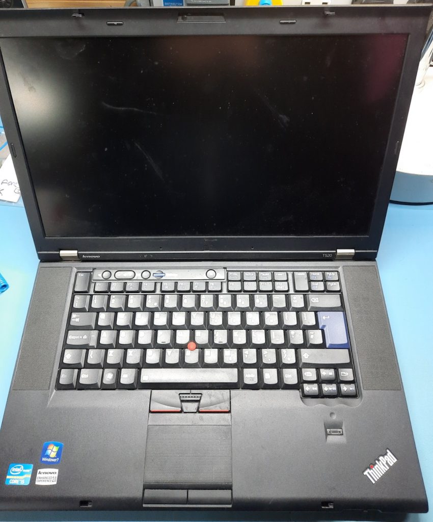
I was looking around the storage rack in my main workshop when I stumbled upon an old Lenovo laptop, specifically a T520 model. These are nicely made, solid machines. They are rather hefty but nice to use. The keyboard and trackpoint are great, and the screen is also OK. This got me thinking; I have two of these (the other is my Minecraft server), and this one is just kinda sitting here with no job to do. Wouldn’t it be cool to remove the boring old PC internals (admittedly, they’re not that bad) and add some custom electronics in there? How about turning it into a CM4-based Raspberry Pi system? Throw in an FPGA and some other magic, and I could build the perfect hacker mobile.
Start By Taking It Apart
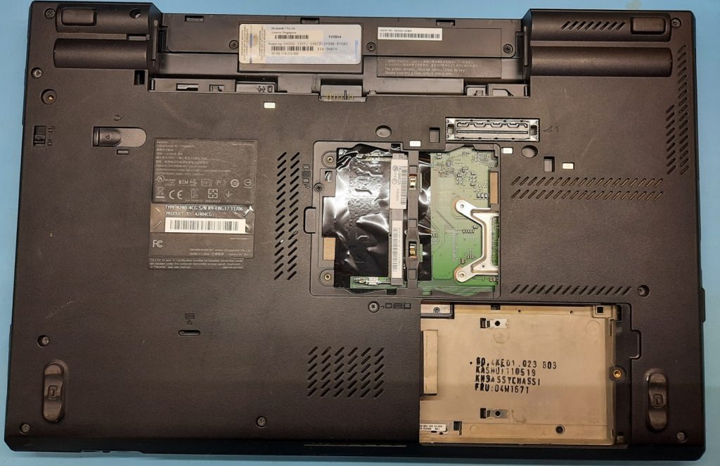
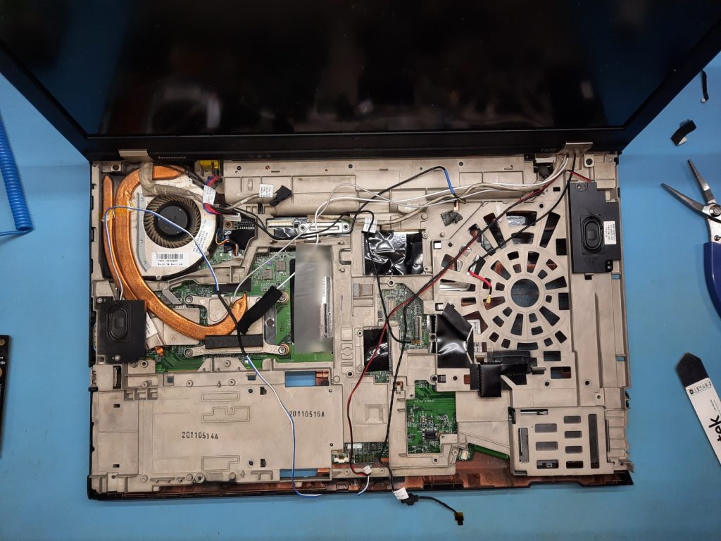
The first job was easy enough—take all the screws out. I carefully removed all the fasteners, taping them back in place so I wouldn’t lose track of which came from where. I plan to reuse only the case, screen, keyboard, TrackPoint, speakers, and the original power supply connector. I’m also hoping to reuse the battery, but if it proves too damaged, I may buy a new one or hack some new cells into the existing plastics. We shall see later on.
This series of laptops has an ‘ultra bay’ expansion port on the right, which often sports an optical disk. Certain Lenovo machines can also accept other peripherals, such as an extra battery, which gave me a second idea. This laptop is going to have a modular expansion port in this location, so I can break out anything I feel like and add new capabilities in the future. Other projects are out there that leverage this space for other means, such as this embedded Raspberry Pi.
Finally, there is also an ExpressCard slot, which is less useful, but since there’s an opening in the case, I’ll need to try to use that for something as well, although I’m not sure exactly what.
The keyboard easily comes out, since it’s only secured by one or two screws below. With a bit of pressure and a firm push toward the display, it simply lifts out, complete with the Trackpoint buttons. Nice!
Here are the replaceable Wi-Fi and GSM radio modules. The keyboard attaches with a single connector on the end of the centrally visible flex cable.

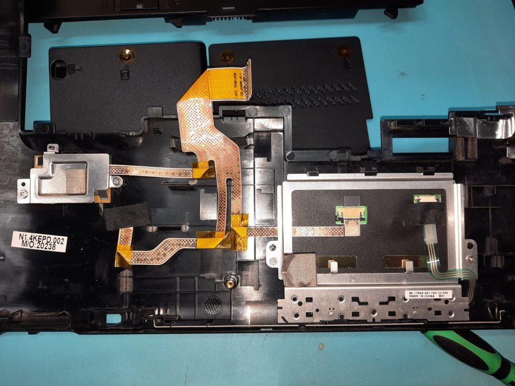
After carefully splitting open the plastic locking tabs with my trusty spudger and removing the palm rest/trackpad assembly, I could access the remaining top-side internals.
Flipping over the palm rest, and looking a little closer, we can see the trackpad and fingerprint scanner details, connected to that shared flat cable. I’ll be keeping the trackpad, but not the dumb fingerprint scanner, which I plan to replace with something more useful, but more on that much later.
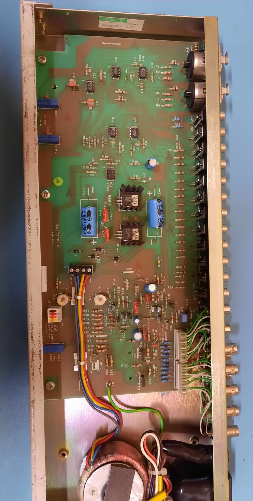
Back to the main unit, and with a bit more spudgering, the bottom plastics are removed exposing the bottom of the mainboard. I already removed the huge heatsink/pipe/fan assembly to expose the CPU and GPU.
This clearly shows the full mainboard outline, including the neat Ethernet/USB sub-PCB in the top right. It is connected via simple edge fingers and a mating connector on the mainboard.
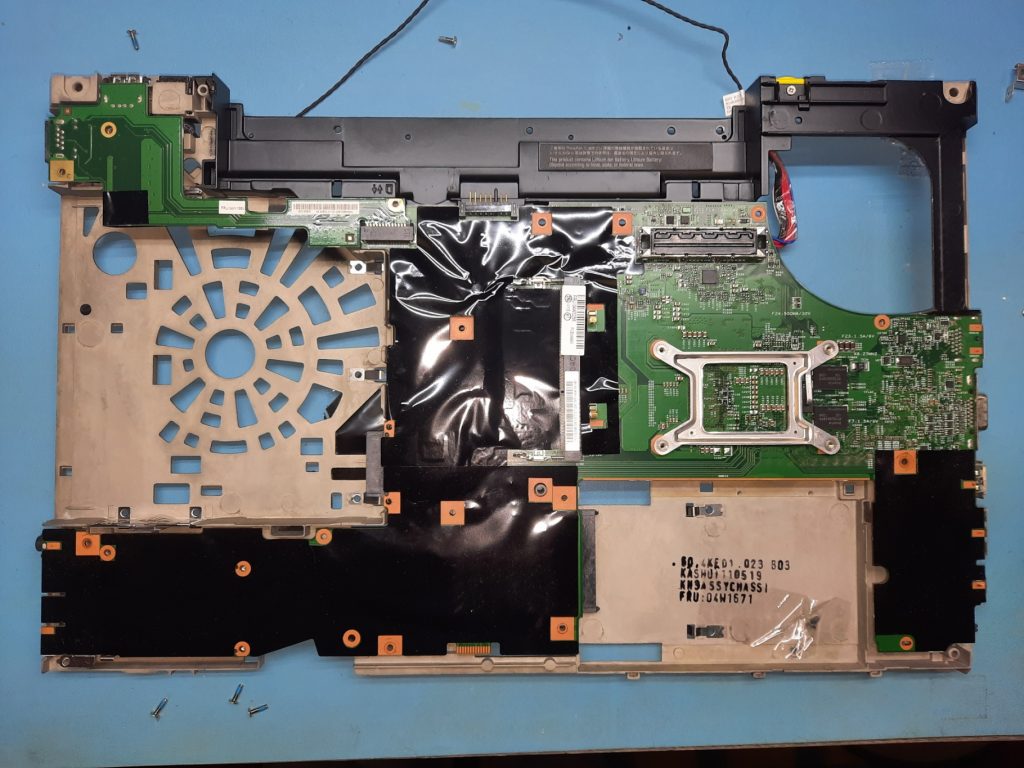
As can be seen above, there is a fair bit of space available on the mainboard outline and a big chunk of space on the left for the expansion area. Bottom-right is the space for the hard disk, which I may keep for this purpose. Top-right is the space for cooling and an exhaust fan. I’ll likely not need all of this for this purpose, so the custom design I come up with may expand into this space.
Whilst it’s not set-in-stone, it would seem sensible to reuse the sub-PCB as-is, as I will still need ethernet and USB connectivity, so why not?
At the top-right there is the standard docking connector (above the CPU clamp, to the right of the black tape) I don’t really have a use for this, and certainly don’t own the docking station for this machine, nor desire to. I may end up simply making a blanking plug for this, or maybe making my own docking plate to either charge the internal battery or add a battery pack. Undecided.
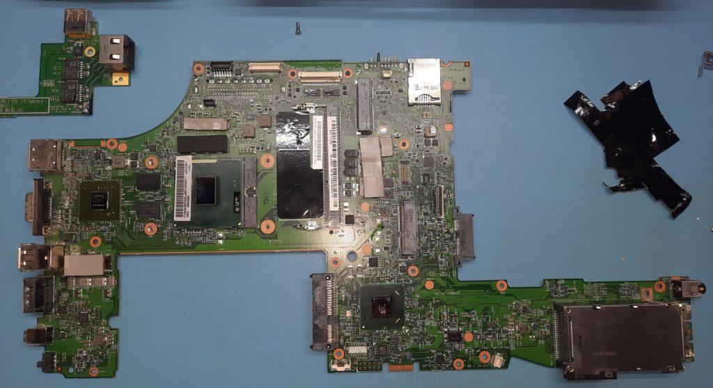
The outline of this mainboard, together with the details of mounting hole sizes and locations, as well as exact part numbers and locations of all externally-facing connectors are all needed before designing a replacement for this board.
Some of the connections will be replicated, e.g. USB, SDCard, and audio, but several ports such as DisplayPort, eSata, and FireWire just don’t make sense and need either blanking off (ugly!) or something else to fit in the holes. I do not want to modify the plastic casing unless I really need to.
Since the CM4 has a few interfaces, it seems obvious to break some more out. the second HDMI port seems like a good choice for at least one dedicated connector, and I could easily add additional ports via dedicated chips on the mainboard, hanging off the USB or PCIe interfaces. The CM4 does not natively support USB 3.0, so I would need at least one external controller hanging on that high-speed bus anyway.
Next Steps and Plan
It’s a little tricky to accurately measure the outline and hole locations on a PCB fully populated on both sides, so the obvious thing to do is to start stripping the mainboard of its parts. I will likely buy a second non-working PCB for this purpose, as this one actually works just fine.
If I simply strip the board of all parts and remove enough solder to get it flat, it is possible to just scan or even photograph the PCB on both sides in order to read off the mechanical details I need. If the connector part numbers are all found, then the footprint can be used to work out the placement details with respect to the external case openings.
Before all of this, it will be a good idea to measure the bounding box of all the larger parts and connectors on the board. This will can be used to add bounding box shapes in the correct locations on the new PCB, to ensure it will fit within the confines of the internal frame and the external casings.
Probably the easiest first step will be to 3D print the Raspberry Pi ultra-bay hack from earlier, and physically insert it to get an idea of the constraints the expansion option might add. I don’t want to get any nasty surprises that limit the possibilities this space gives, or have to respin the PCB purely because of a silly mechanical error.
The Plan
- 3D print expansion bay plastics
- Measure mainboard bounding boxes
- Strip the PCB of parts and identify major connectors (this also goes for internal connectors like the PCB connector)
- Measure (accurately) PCB outline shape, mounting holes, and connector footprints
- Draw the outline and add mechanical details to the PCB project (KiCAD, obviously!)
- Laser cut the above from 1.5mm acrylic and test fit into the frame and casings
- Iterate!
I may also 3D print some bounding boxes for larger parts to check for any obviously limited clearances, and feed that back into the design by using the 3D files as dummy PCB part models.