At some point, pretty much anybody who does electronics prototyping needs to master reflow soldering. There are a few ways to do it.
The simplest is to set up the PCB with solder paste and components pre-applied on a preheater to get it up to a starting temperature. Then, apply the additional reflow heat with hot air from above. Such equipment can be had for little outlay from the usual suppliers.
Example, very basic pre-heater
This is fine for one-off prototypes or very small quantities. However, temperature control is difficult for fine-pitch parts. Anything really sensitive, like MEM devices, will suffer, and sometimes, it’s just hard to get enough heat into some boards at all.
How the factories do it
The factories use a conveyor system feeding into a multi-zonal convection oven. The preheat-reflow-cooldown profile is achieved by having zones at different temperatures and passing the boards through them sequentially. The convection part is important, as it ensures all the heat is spread uniformly throughout the zone, so the PCB is heated evenly with the parts.
Another important aspect of a modern convection oven is that it does not directly heat the PCB with the heater units but actually relies on secondary emission from metal or ceramic platens. The heaters themselves, whatever technology they use, are enclosed, so the intense IR radiation is absorbed only by the platens. This then re-radiates the heat as blackbody radiation (much longer wavelength IR), assisted by forced convection fans.
The nice thing is that the heaters themselves do not need to change temperature, as each zone is controlled precisely at one part of the temperature profile, and the ramp-up-down is achieved by physically moving the boards between zones. This means that the heating profile is independent of the heaters’ performance, which allows for better efficiency.
This is the gold standard used today.

Desktop Reflow
I can’t fit such a thing in my workshop, even if I could afford the cost.
So, the next best thing is a desktop reflow oven. The choices are either to buy one or build one.
There are many cheaper ones available from the usual Chinese brands, with varying performance. Decent quality units can be purchased from more specialised suppliers, which are pretty expensive. My plan is to repurpose a standard toaster oven, with some temperature measurements and some power control
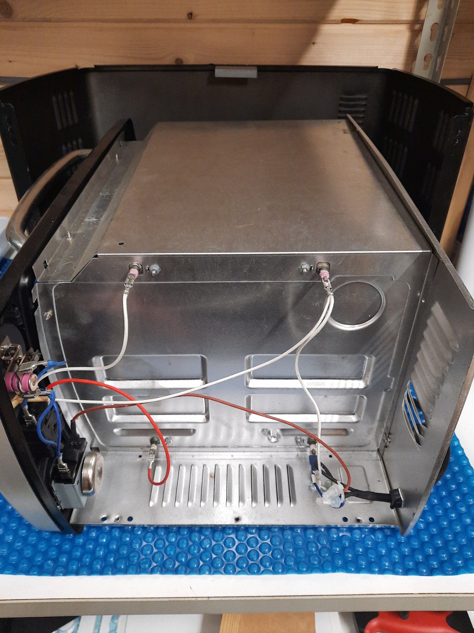
Here it is in all its glory:
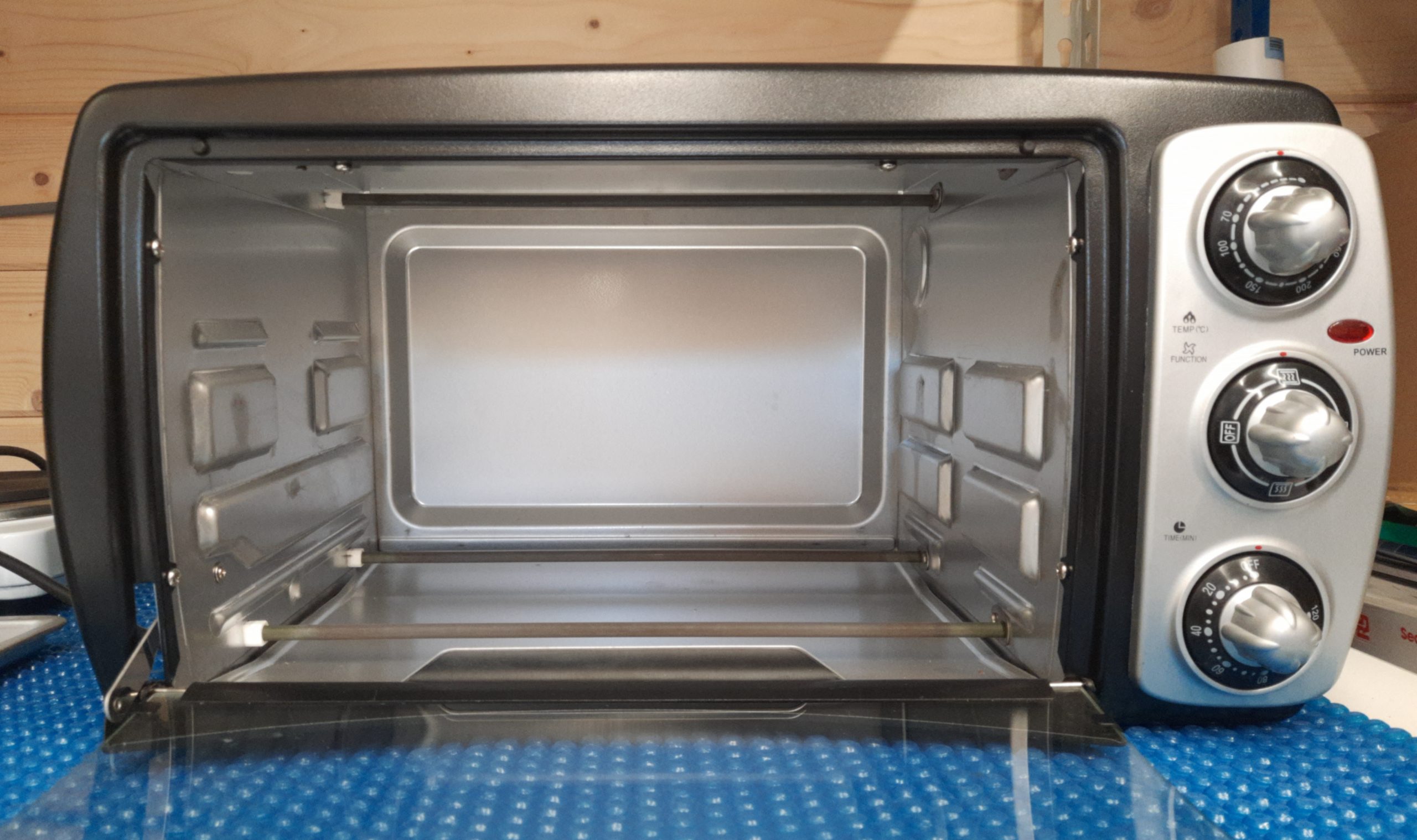
As can be seen, this uses four calrod resistance heater elements.
It seems like a simple concept, but there are immediate problems.
Issue 1: Heat up
Firstly, the power. There is a lot of space in there. PCBs are flat, and surface-mounted components are also not very tall. We aren’t going to solder a turkey to the board, so we don’t need so much volume.
Lots of volume means lots of air, and lots of air means lots of heat needs to be dumped into it from the heaters to get it to temperature. This will result in a sluggish heat-up rate, making it hard to follow the correct temperature profile at best. At worst, the excessive heating time will cause permanent damage to sensitive parts.
The solutions to this are pretty obvious: reduce the air volume, maximise the heater power, use fast heating elements, and finally, reduce heat losses with insulation.
Issue 2: Cool Down
The next main problem is what happens after the reflow point is reached. We need the temperature to drop back down to ambient within a fairly short time. A big toaster oven will retain all that heat and take an age to cool. This could cause damage due to excess heat and just waste my time waiting around.
The only realistic solution is to exhaust the hot air into the environment, either with a valve or just by forcing the door open. An exhaust fan would help here. However, that fan needs to be able to withstand air at nearly 300℃, which makes it a little awkward to find.
Issue 3: Differential Heating
Finally, the method of heating is wrong. The toaster oven heating elements will radiate a lot of IR radiation (we like to call it ‘heat’) which will be absorbed more strongly by dark things (like those little black squares, with all those tiny, sensitive circuits) The other bits, the fiberglass PCB Substrate and the shiny, reflective PCB solder lands will absorb less rapidly.
This means the chips will heat up far faster than the solder lands, so by the time the latter is hot enough to melt the solder balls, the chips and any larger components could well be far too hot.
In order to get the solder to melt uniformly, even more heat needs to be dumped into the board, risking overheating in some areas. This will result in the formation of solder balls or, worse, charring of the solder flux.
Solder balls are a nightmare for fine-pitch work, and burnt flux makes cleaning much harder. It’s best not to overheat it then.
Anything that can be done to block this direct heating will help. Remember when I talked about convection ovens earlier?
Issue 4: Shadowing
The last problem that direct heating causes is shadowing. This is when a larger part absorbs heat from the heating element and casts a shadow on the parts close to it, so they don’t heat as fast. Also, the solder lands directly below a part like an IC, and it will be in the shadow of the IC itself, so it will also not heat up as quickly as it could. Convection ovens also solve this problem.
The only solution I can think of is blocking the direct heat path by adding metal shielding and ensuring the heat can escape with air circulation.
The Plan
It may turn out that even with some serious modifications, this will not be very well suited to soldering. However, it will still be very useful for baking PCBs post-cleaning and for baking moisture-absorbing parts (higher MSL) prior to placement. We shall see by just building it.
- Add a high-temperature thermocouple or PTC probe near the PCB shelf. The usual sites sell thermocouple amplifiers with an I2C interface. However, you need to check specifications carefully, as eBay is flooded with thermocouples that aren’t rated for reflow temperatures.
- Build a proportional power controller, using an SSR and Arduino or similar. I’ll probably use a small LCD display shield to allow profile selection and show progress.
- Add some internal metalwork to reduce volume. Add some insulation around the internal part of the case
- Locate a high-temperature squirrel-caged (or centrifugal) fan for circulation
- Locate a high-temperature exhaust fan and rotary valve. Perhaps the latter can be an externally mounted servo motor
- Build perforated baffle plates around the heater elements to allow hot air to pass, but block direct IR radiation